Abstract
This study explores the stereolithography process for ceramic material, identifying defects and evaluating the characteristics of the fabricated parts. Each stage of the process (printing, cleaning, debinding, and sintering) is analyzed with a focus on material transformations and defect formation. Defects such as non-uniform material distribution, superficial damage from cleaning procedures, and residual organic compounds were identified in the printing, cleaning, and debinding stages. The sintering process revealed uneven consolidation, with varying degrees of particle bonding and residual porosity, highlighting the need for optimized thermal treatments. Surface roughness and dimensional analysis indicated the influence of printing orientation and thermal treatments on the final surface quality and shrinkage behaviour. Additionally, the study examined edge geometry and hardness, confirming that SLA technology can produce sharp edges and ceramic components with mechanical properties comparable to those of conventionally manufactured alumina. These findings underscore the importance of optimizing post-processing stages to minimize defects and improve part quality and performance of printed ceramic components for advanced applications.
Keywords Stereolithography · Ceramic · Aluminum oxide · Debinding · Sintering
1 Introduction
Additive manufacturing (AM) offers an alternative to traditional processes, making it possible to manufacture geometrically complex ceramic parts without using expensive tools. However, the implementation of AM technologies in the ceramics industry is being much slower than in the polymer and metals industries. Among the various AM technologies applied to ceramics, a broad distinction can be made between single-step and multi-step processes. Single-step approaches, such as powder bed fusion (PBF) [1], consolidate ceramic components directly during fabrication without the need for post-processing. Nevertheless, these methods present critical limitations when applied to ceramics due to the high melting temperatures required, low absorptance of ceramic powders, and the high risk of thermal shock and cracking. As a result, most advanced ceramic AM technologies rely on multi-step processes, which involve printing a “green body” followed by thermal consolidation through debinding and sintering. These include material extrusion (MEX) [2, 3], binder jetting (BJT) [4, 5], material jetting (MJT) [6], and vat photopolymerization (VPP). Among these, VPP has demonstrated superior capabilities for producing ceramic parts with mechanical properties, precision, and surface finish comparable to injection molding components [7]. This is largely due to the precise control of photopolymerization kinetics and the use of highly loaded ceramic slurries.
Within the VPP technologies, stereolithography (SLA), designated as VPP-UVL/C according to ISO/ASTM 52900:2021, stands out as a promising technology for manufacturing oxide ceramics such as alumina, zirconia, and hydroxyapatite [8, 9]. The top-down configuration of SLA systems enables the use of highly viscous, high-solid-loading pastes, which are essential for achieving dense, high-performance ceramics after sintering. While MEX and BJT technologies offer greater scalability in terms of build volume and speed, they often result in lower resolution, increased surface roughness, and higher porosity, which necessitate more intensive post-processing. In contrast, SLA enables finer resolution and more uniform feature definition, offering superior control over complex geometries compared to MEX processes that are constrained by nozzle diameter and path limitations. Furthermore, SLA technology is currently the most industrially adopted AM technique for advanced ceramic fabrication, with multiple commercial systems available and under active development. Despite its potential, several challenges remain to be addressed for ceramic SLA to achieve full industrial adoption.
In VPP-UVL/C technology, a ceramic slurry, composed of fine ceramic powder and an organic binder, is transformed into a solid part by the action of ultraviolet light, which selectively polymerizes the organic binder to hold the ceramic particles together. The printed green part is then subjected to a cleaning process to remove the uncured material. This stage is followed by thermal treatments, including debinding and sintering. During the debinding stage, the organic binder material is burned off, partially consolidating the ceramic particles. The subsequent sintering process fully consolidates the ceramic particles, resulting in the final ceramic part [10]. These post-treatments are critical for the integrity of the parts, especially the debinding stage. The organic binder, which is incorporated into the ceramic paste, is essential during the printing phase to provide the necessary viscosity and mechanical resistance to the green parts; however, it is necessary to remove it in a very controlled way [11]. The removal process must be carried out gradually to avoid differential contractions, warping, delamination, or cracks in the parts [12]. On the other hand, incomplete removal of the binder can result in carbon residues that degrade the mechanical properties and purity of the ceramic parts, ultimately compromising their performance [13]. Successfully completing the debinding stage requires very long cycle times carried out in an inert atmosphere, resulting in extended processing times and high costs [14,15,16]. Additionally, the debinding process limits the maximum thickness of the parts to ensure that gases can escape without causing delamination or cracks [17]. Another critical challenge is the shrinkage that parts undergo during sintering [18]. This shrinkage impacts dimensional accuracy, varying across different build directions, making it challenging to achieve precise dimensions in complex geometries [19].
Considering the aforementioned challenges, further advancements in VPP-UVL/C technology are essential to establish it as a truly competitive alternative to conventional ceramic manufacturing methods. While several studies have examined individual stages of the SLA process, particularly focusing on debinding [11], few have systematically examined the complete process chain and its cumulative effects on final part quality. Moreover, limited attention has been given to the origins and evolution of defects throughout the process chain, particularly those associated with the cleaning stage. This study provides an integrated experimental assessment of all four stages under realistic processing conditions, specifically for alumina parts. We investigate the influence of each stage on key part characteristics, including defect formation, microstructural evolution, dimensional accuracy, surface roughness, and hardness.
2 Methodology
To conduct this study, a total of 15 specimens in the form of 5 × 5 × 5 mm cubes were fabricated. A small hole was designed on the top surface of each cube to identify the printing orientation. The dimensions were set based on the thickness limitations for this material, which are restricted to 5 mm for flat shapes. This constraint is due to the significant release of gases during the thermal decomposition of the organic binder. In thicker samples, inefficient gas escape can cause internal pressure buildup, increasing the risk of fractures in the debinded part. The alumina (Al2O3) paste used was provided by 3D CERAM (Limoges, France) and consists of alumina powders mixed with photosensitive resins. The detailed formulation of the paste remains undisclosed by the manufacturer.
The following sections describe the four stages involved in the manufacturing process (printing, cleaning, debinding, and sintering) and outline the techniques and equipment used to evaluate the quality of the fabricated ceramic parts.
2.1 Printing and cleaning of alumina green specimens
The printing process was carried out using a Ceramaker 900-Flex machine under the printing conditions recommended by the manufacturer (3D CERAM, Limoges, France). The printer operates with a top-down configuration, where the build platform is positioned above the resin vat and moves downward during printing. The ultraviolet laser light source, with a wavelength of 355 nm and a spot diameter of 35 µm, is located above the resin vat. This setup supports the use of more viscous ceramic slurries. The build platform measures 300 × 300 mm, with a maximum build height of 100 mm. Printing resolution is approximately 30 µm in the x/y directions and 10 µm in the z direction. Key printing parameters were set as follows: laser power at 375 mW, layer thickness of 50 µm, laser scanning speed of 5 m/s, scanning pattern in a grid with a hatch distance of 0.05 mm, and recoating speed of 0.5 m/s. All specimens were printed using the same parameter set to ensure consistency throughout the study. After printing, the green parts required cleaning to remove uncured resin from their surface. All specimens were cleaned using pressurized air and chemical solvents specifically formulated by 3D CERAM. The pressurized air was applied at a pressure between 2 and 3 bar, sufficient to effectively remove the uncured slurry.
2.2 Debinding and sintering processes
The debinding process for green bodies was conducted in a tubular furnace with atmosphere control (Ceradel PTF 16/130/610), while the sintering process was carried out separately using a different furnace (HTL 20/17). For both processes, the curves recommended by the manufacturer were used, which are established to achieve parts with minimal porosity and free of delamination or cracking. The debinding process reached a maximum temperature of 1200 °C, with different heating rates and dwell times. The total cycle lasts 89 h (approximately 4 days) of which 74 h were conducted under a nitrogen atmosphere. The sintering process reached a maximum temperature of 1700 °C, with a total cycle time of 21 h.
2.3 Analysis of defects and properties of alumina ceramic parts
Scanning electron microscopy (JEOL 6480, Tokyo, Japan), equipped with an energy dispersive X-ray spectroscopy (EDS), was used to evaluate the microstructure and transformations that occur during thermal treatments, as well as to identify the causes of defects appearing at different stages of the process. Five samples were examined at each stage (printed and cleaned, debinded, and sintered). For the sintered specimens, surface roughness was measured on five parts, distinguishing between the top, bottom, and lateral surfaces, with three measurements taken on each surface. An optical measurement system (Alicona Infinite Focus) was used for this purpose, and the Sa parameter was recorded. Dimensional measurements were taken after the printing, debinding, and sintering stages to assess printing accuracy and shrinkage in each step. Measurements were performed along the X, Y, and Z axes using a digital micrometer with an accuracy of 0.001 mm. For each stage, measurements were taken on five specimens, and each measurement was repeated three times to ensure data reliability. The study included an evaluation of edge geometry with particular focus on changes in edge radius induced by the thermal treatments. Measurements were carried out for the edge radius between the top and vertical surfaces, as well as between the two vertical surfaces. The Vickers micro-hardness was measured using a 9.8 N load and a dwell time of 15 s. Hardness tests were conducted on the final sintered specimens using a microdurometer (Shimadzu HMV-2000). Twelve indentations were performed in both the perpendicular and parallel directions relative to the layers to evaluate the inherent anisotropy associated with additive manufacturing processes.
3 Results
This section presents the results obtained from the analysis performed on the ceramic parts at the different stages of the SLA process.
3.1 Defects produced in the printing and cleaning stage
During the printing process, the alumina paste is deposited on the printing platform in layers of 50 µm thick. The material does not always spread uniformly, generating areas with voids and others with trapped bubbles. Figure 1a shows an image of the paste spread on the platform, where these voids and bubbles are evident. When these defects coincide with the areas intended for the parts, irregularities are generated both inside and on the surface of the printed components, as illustrated in Fig. 1b and c. To minimize these problems, two key strategies can be applied: first, adjusting the blade speed to ensure more uniform material deposition; second, developing a paste formulation with optimal rheological properties and free of bubbles. The combination of these factors is essential to achieving layer uniformity and preventing structural defects in the manufactured parts.
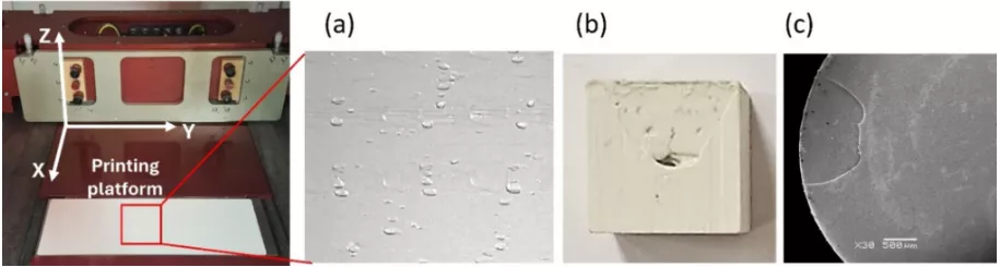
Fig. 1 a Printing platform of the Ceramaker 900 machine and material distribution defects. b Printed part with cavity defect. c SEM image showing a surface defect on the part
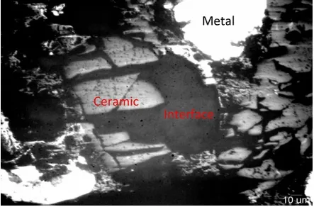
The cleaning stage, essential for removing uncured material, can introduce defects in the parts. The application of pressurized air combined with chemical solvents can damage the surface. In Fig. 2, linear grooves and areas of displaced material are visible, suggesting that excessive jet pressure has removed more material than necessary, compromising surface uniformity. These surface defects generated during the cleaning stage persist and are not eliminated in subsequent processing steps, remaining in the final sintered part, as seen in Fig. 2b and c. This highlights the importance of carefully optimizing the cleaning process, including jet pressure and solvent application, to minimize surface irregularities.
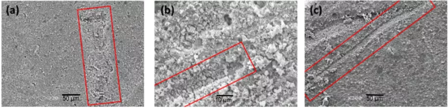
Fig. 2 Surface defects caused by cleaning: a printed and cleaned surface, b debinded surface, c sintered surface
Another defect introduced during the cleaning stage is the presence of residues from the cleaning solution. SEM analysis of the surface revealed potassium chloride (KCl) residues (Fig. 3). These impurities can cause defects during the debinding stage, as their removal could lead to pores or imperfections in the part. To ensure thorough cleaning and to remove impurities present on the surfaces of green parts, specimens can be subjected to an immersion cleaning process using an acid, such as hydrofluoric acid (HF).
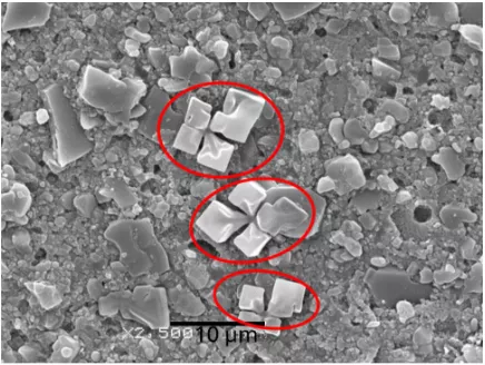
Fig. 3 KCl residues on sample surface after cleaning
3.2 Microstructure evolution of Al2O3 during debinding and sintering treatments
The debinding treatment aims to remove the organic material present in the part and perform a pre-sintering that provides sufficient consistency for handling before sintering. However, images obtained by SEM reveal the presence of organic material in the sample (Fig. 4), even though their complete decomposition should occur in a thermal range of 500–600 °C. The persistence of these organics residues suggests a non-homogeneous removal of the binder, possibly associated with the formation of aggregates in the resin or incomplete combustion during the final debinding stage in an oxygen atmosphere. Additionally, the presence of elongated structures on the surface of the specimens suggests a possible re-solidification of organic compounds or a segregation of phases during thermal degradation. This phenomenon highlights the need to optimize temperature ramps and dwell times during debinding or even reconsider the formulation of the precursor material.
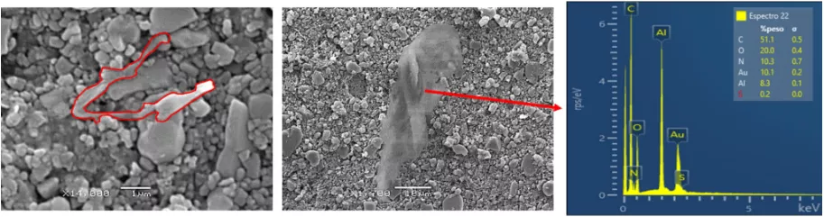
Fig. 4 Organic material residues present in the sample after debinding
The SEM analysis carried out on the sintered samples showed that the sintering has not been homogeneous throughout the sample. Areas with different degrees of particle consolidation were identified. Figure 5a shows particles joined by interconnected necks and porosities, characteristic of the initial phase of sintering, where the surface diffusion begins to form the first bonds between the particles. Figure 5b shows an area with a more advanced state of particle-bonding, evidenced by an increase in the contact area and a reduction in interparticle porosity. Intraparticle pores with a rounded shape are observed, resulting from the reconfiguration to minimize surface energy. Finally, Fig. 5c illustrates a region with an advanced state of compaction, where the particles have fully consolidated, giving rise to large crystalline grains and minimal residual porosity.
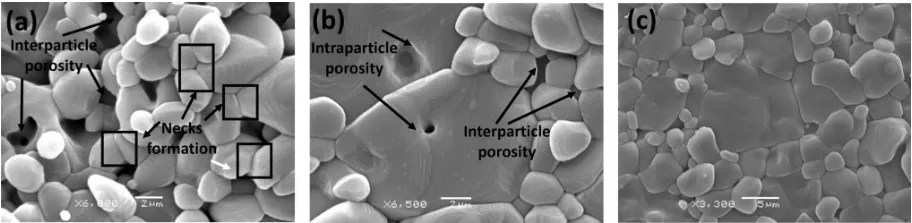
Fig. 5 SEM images in sintered samples showing different states of consolidation of the particles
These differences in microstructure indicate a non-uniform consolidation of the material during the sintering process, which could compromise the mechanical properties and quality of the final component. These observations highlight the need for more precise adjustments to sintering process parameters, such as the temperature–time ramp and furnace atmosphere, to ensure greater homogeneity and enhance the quality of the final product.
3.3 Surface quality
An anisotropic character was observed in the surface quality of the sintered ceramic parts. The average value for Sa was 0.725 ± 0.26 μm on the horizontal top surface, 0.673 ± 0.18 μm on the horizontal bottom surface, and reached 1.975 ± 0.39 μm on the vertical surface along the fabrication direction. Figure 6 shows the images obtained for the different surfaces. On the vertical surface, the roughness profile is also shown in the OZ direction corresponding to the construction of the part, where the 0.50 μm thick layers can be seen. The bottom surface exhibited lower roughness, which could be attributed to the initial printing layer deposited by the laser across the entire build platform to ensure part adhesion and prevent displacement by the recoater blades during the deposition of subsequent layers. Additionally, this lower roughness may result from the fact that this surface remained in contact with a support surface during the debinding and sintering stages, potentially undergoing different modifications compared to free-standing surfaces. This aspect requires further investigation.
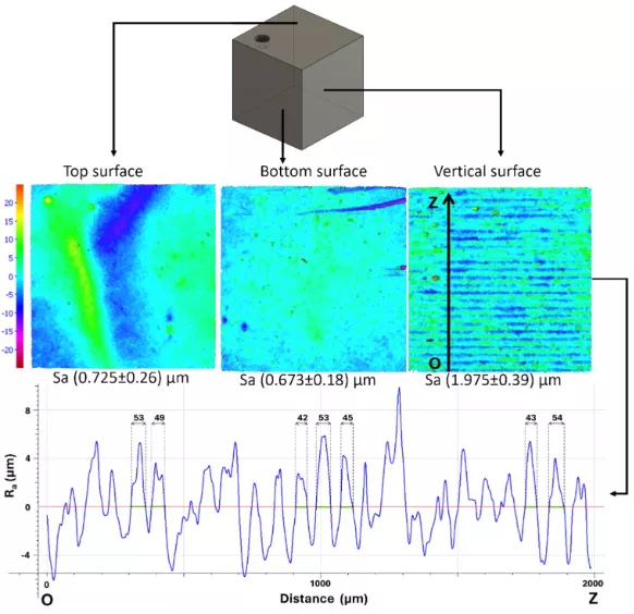
Fig. 6 Surface roughness (Sa) measurements of the top, bottom, and vertical surfaces of the sintered samples, obtained using Alicona Infinite Focus
3.4 Dimensional accuracy
The average dimensional values of printed, debinded, and sintered alumina ceramic parts are shown in Fig. 7. The printed specimens were slightly larger than the CAD design (5 × 5 × 5 mm cubes) due to overcuring, a phenomenon where an excessive curing area compared to the projected area impacts the printing accuracy. Overcuring occurs as a result of light scattering caused by the difference in the refractive index between ceramic particles and the photocurable resin [20]. The measurements of the specimens after debinding showed a slight shrinkage of 1.1%, 1.5%, and 0.3% in the Y, X, and Z directions, respectively. This shrinkage is due to the fact that during debinding, temperatures of up to 1200 °C are reached, which causes slight presintering and, consequently, shrinkage. The shrinkage in the Z direction was lower because gases from the binder decomposition escaped more easily through the layers, leading to layer separation and reducing interlayer particle consolidation. If this separation becomes too severe, it can result in delamination. During sintering, the material exhibited significant shrinkage, with linear contractions of 12.1%, 13.5%, and 14.5% in the Y, X, and Z directions, respectively. Unlike the debinding stage, the Z direction showed the highest shrinkage. As previously mentioned, layer separation and void formation are more prominent along the build direction. The sintering process promotes interlayer bonding and void reduction, resulting in greater shrinkage along this axis. Understanding the shrinkage process is necessary for optimizing geometric design and ensuring dimensional accuracy in SLA ceramic parts.
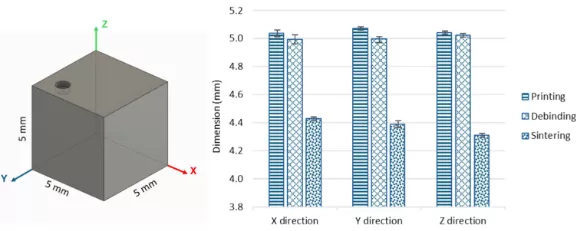
Fig. 7 Dimensions of printed, debinded, and sintered Al₂O₃ ceramic parts
The capability of VPP-UVL/C technology to manufacture parts with sharp edges has been analyzed. The edge geometry of all printed, debinded, and sintered cubes was measured using an Alicona Infinite Focus microscope, and the edge shape was characterized using the method developed by Denkena [21] for cutting-edge characterization. Although the cube edges were designed in the CAD model without any applied rounding, the manufactured edges are not perfectly sharp, exhibiting a certain degree of rounding. Figure 8 presents the measured edge radius at two locations: between the top and vertical surfaces, and between adjacent vertical surfaces. The radius corresponding to the top-to-vertical edges were always smaller than those between the vertical faces. In all cases, the green parts showed the smallest edge radius, which increased after the debinding stage. After sintering, a reduction in edge radius was observed, attributed to the overall shrinkage of the part. These values represent the minimum achievable edge radius that can be obtained in parts manufactured using SLA technology with the studied alumina material. Nonetheless, this limitation does not compromise the applicability of the process, as excessively sharp edges are generally undesirable in ceramic components due to their susceptibility to stress concentration and fracture.
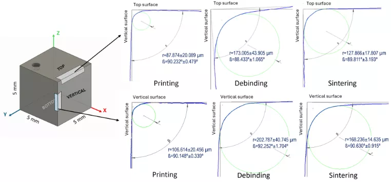
Fig. 8 Edge radius between the top and vertical surfaces and between adjacent vertical surfaces of printed, debinded, and sintered Al₂O₃ ceramic parts
3.5 Hardness of 3D printed Al2O3 ceramic parts
The Vickers hardness of the specimens was evaluated by performing indentations on the top and vertical surfaces. The average hardness values from 12 measurements were 16.89 ± 0.72 GPa on the top surface and 15.34 ± 0.91 GPa on the vertical surface. The obtained values and the morphology of the indentations were very similar on both surfaces, indicating no anisotropic behaviour regarding hardness. The hardness of the samples is comparable to the hardness values of alumina obtained by conventional methods.
Although anisotropic behaviour was observed in terms of shrinkage and surface roughness due to the layer-by-layer fabrication, the hardness remained relatively uniform across different orientations. This behaviour suggests that the microstructural consolidation achieved during sintering, including grain bonding and densification, was sufficiently homogeneous throughout the volume of the parts, resulting in an isotropic mechanical response. Similar observations have been reported in previous studies [22, 23], which found no significant anisotropy in hardness despite directional differences in other properties of SLA-printed ceramics parts. Nevertheless, there is a lack of studies that specifically investigate anisotropic microstructural changes in ceramics induced by build orientation, as has been extensively explored in metallic materials [24].
4 Conclusions
This study analyzed the stages of the ceramic SLA manufacturing process, identifying defects involved in each stage and evaluating the characteristics of the fabricated parts. In the printing stage, defects related to non-uniform material distribution and dimensional inaccuracies were identified. During the cleaning stage, material dragging and residues from the cleaning solution led to persistent defects in the final part. Additionally, the presence of residual organic material after debinding indicates incomplete binder removal. In the sintering stage, although densification and microstructural consolidation occurred, regions with varying degrees of particle consolidation and porosity were observed. These results highlight the need to optimize cleaning, debinding, and sintering post-processes to achieve defect-free surfaces, homogeneous densification, and minimized porosity in ceramic parts.
The surface roughness analysis revealed that the highest roughness was observed on the vertical surface along the build direction. The lower roughness of the bottom surface may be attributed to the initial printing layer and its contact with the support surface during thermal treatments, highlighting the influence of printing orientation and processing conditions on surface quality. The dimensional analysis revealed anisotropic shrinkage, with the highest contraction observed in the Z direction during sintering due to interlayer bonding and void reduction. Additionally, the analysis of edge geometry showed that while some rounding occurred throughout the process, SLA technology can produce relatively sharp edges suitable for ceramic components. Finally, it was confirmed that the samples exhibit an isotropic hardness behaviour, reaching levels comparable to those of alumina obtained by conventional methods.
Despite advancements in SLA technology for manufacturing ceramic parts, several limitations inherent to the process remain to be addressed. Among them, the debinding stage continues to be one of the most critical constraints, due to the complex thermal behaviour of different ceramic–binder systems, which prevents the establishment of standardized debinding profiles applicable to a wide range of materials. Moreover, the fabrication of parts with substantial thickness remains challenging, as they are more susceptible to cracking and delamination during thermal treatments. The debinding stage is also time- and energy-intensive and generates waste gases, highlighting the need for the development of more energy-efficient and environmentally sustainable alternatives. Another critical area for improvement is the cleaning stage, which remains a manual and time-intensive process, especially for components with complex geometries. To enable the transition from laboratory-scale to industrial-scale production, the development of automated and reproducible cleaning strategies will be essential.
References: Omitted
Declaration: This article is provided by CERADIR™ users or obtained from Internet, the content does not represent the position of CERADIR™. We are not responsible for the authenticity/accuracy of the article, especially the effects of the products concerned. This article is for study only, it does not constitute any investment or application advice. For reprinting, please contact the original author. If it involves the copyright and/or other issues, please contact us and we will deal with it asap! CERADIR™ has the interpretation of this declaration.