Abstract: The SiBCN matrix via chemical vapor infiltration (CVI) or/and polymer infiltration pyrolysis (PIP) technologies was orderly introduced to SiCf/SiC composites to optimize the mechanical property and electromagnetic (EM) shielding effectiveness simultaneously. The BN interface with the thickness of 350 nm was designed to obtain a little stronger interface bonding. The flexural strength of SiCf/SiC-SiBCN composites reached 545.45±29.59 MPa thanks to the crack deflection between the CVI SiC and CVI SiBCN, as well as CVI SiBCN and PIP SiBCN matrix because of the modulus difference between them. The fracture toughness (KIC) with the value of 16.02±0.94 MPa·m1/2 was obtained owing to the extension of crack propagation path. The adverse effect of stronger interface bonding was eliminated by the design of matrix microstructure for SiCf/SiC-SiBCN composites. The thermal conductivity in the thickness direction was 7.64 W·(m·K)−1 at 1200 °C and the electric resistivity decreased to 1.53×10³ Ω·m. The tunable dielectric property was obtained with the coordination of wave-absorption CVI SiBCN matrix and impedance matching PIP SiBCN matrix, and the total shielding effectiveness (SET) attained 30.01 dB. It indicates that the SiCf/SiC-SiBCN composites have great potential to be applied as structural and functional materials.
Keywords: SiCf/SiC–SiBCN composites; chemical vapor infiltration (CVI); polymer infiltration pyrolysis (PIP); mechanical property; electromagnetic characteristic
1 Introduction
SiCf/SiC composites have been widely investigated as a significant thermo-structural material in aero-engine and fusion reactor structural application because of the excellent characteristics (e.g., the low density, high specific modulus and strength, high toughness, oxidation resistance, etc.) [1,2]. Nevertheless, the matrix microcracks, resulting from the nonlinear mechanical characteristic when the SiCf/SiC is loaded, as the diffusion channels of oxidizing medium markedly decrease the service life [3]. The SiBC matrix acting as self-healing component was introduced to SiCf/SiC composites. With the formation of glass phase, the SiCf/SiC–SiBC composites exhibited outstanding mechanical property after exposing in air for 100 h at 800–1200℃ [4]. Above 1200℃ , the self-healing ability of SiBC is insufficient because of its poor thermal stability and the sealing rate [5]. Another self-healing component with excellent thermal stability and self-healing performance is urgently needed.
SiBCN ceramic has low density (1.8 g/cm³), small thermal expansion coefficient, good oxidation resistance (suitable for applying in air up to 1500℃), high temperature resistance (suitable for applying in inert environment up to 1800℃ ) [6], and outstanding creepresistance property [7], which has attracted extensive attention. The good thermal stability makes it widely used in thermal-structure unit and three aspects remain to be studied. Firstly, the mechanical property of SiBCN matrix modified SiCf/SiC composites may be different from that of SiCf/SiC composites resulting from the modulus difference between SiBCN and SiC. Secondly, the SiBCN matrix via chemical vapor infiltration (CVI) process shows continuous and dense morphology, and the dielectric property is tunable by controlling the deposition parameters [8,9]. The SiBCN matrix via pyrolysis (PIP) technology exhibits porous microstructure with some randomly distributed microcracks (owing to the volume shrinkage during the transformation from organic polymer to inorganic ceramic), and the permittivity is low with insulation characteristic [10–12]. The excellent electromagnetic (EM) shielding effectiveness, based on the matrix composition design using wave-absorbing CVI SiBCN and wave-transmitting PIP SiBCN, may be achieved. The impedance matching PIP SiBCN should be located externally to ensure the entry of electromagnetic wave (EMW) and the wave-absorbing chemical vapor infiltration (CVI) SiBCN should be introduced internally to attenuate the EMW. The SiBCN matrix should be orderly inserted into SiCf/SiC via CVI and PIP technologies. Thirdly, the borosilicate or SiO2 glass generates in virtue of the oxidation of SiBCN at high temperatures and oxidizing atmorsphere [13–15]. The self-healing performance can be obtained via viscous flow of borosilicate glass or SiO2, and the service life of SiBCN matrix modified SiCf/SiC composites can be prolonged [16]. The SiCf/SiC–SiBCN composites are expected to be used in structural and functional integration area.
In this contribution, the SiCf/SiC–SiBCN composites with different relative contents of CVI SiBCN and PIP SiBCN matrix were fabricated. The 350 nm-BN interface was chosen to obtain a little stronger bonding between fiber and matrix. The crack deflection was designed to occur at the interface between different matrices in addition to BN interface to extend oxygen diffusion path at matrix. The time for oxygen diffusion from matrix to BN interface and fiber would be prolonged. The BN interface and SiC fiber can be protected from corrosion and the duration of SiCf/SiC–SiBCN composites is greatly increased. The microstructure and phase composition were carefully investigated. The electrical resistivity and thermal conductivity were measured. The flexural strength and KIC at room temperature were tested, and the failure and toughness mechanism were discussed. The differences of mechanical behavior between SiCf/SiC and SiCf/SiC–SiBCN composites were presented. The S-parameter was further obtained in X-band and the EM shielding effectiveness was calculated.
2 Experimental
2. 1 Raw materials
The near-stoichiometry SiC fiber (SiCf) [17] was purchased from Xiamen University, China. The content of O is 0.42 wt% and the atomic ratio of C/Si is about 1.05. Each bundle contains 500 filaments. The diameter is about 12.5 μm and the tensile modulus is 341.85 GPa. The polyborosilazane [18] (PSNB, Institute of Chemistry, Chinese Academy of Sciences, China) was used as the polymer precursor.
2. 2 Experimental procedure
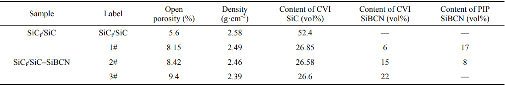
The two-dimensional plain weave SiC fiber cloth was stacked and clamped with porous graphite moulds. The BN interface and SiC matrix were orderly deposited in SiCf preform [19]. The semi-densified SiCf/SiC composites with the density of 2.0 g/cm³ were obtained. Then, SiCf/SiC–SiBCN composites were acquired with the introduction of SiBCN matrix into semi-densified SiCf/SiC composites. The CVI process was firstly chosen to fill the residual small pores between SiCf bundles, and the big holes between the layers were finally divided into small holes by PIP technology. The SiBCN was deposited in semi-densified SiCf/SiC via SiCl3CH3–BCl3–NH3–H2–Ar system at 950℃ . The fluxes of inlet gases were selected as follows: [BCl3]:[NH3]:[Ar]:[MTS]:[H2] = 0.96:0.79:8.21:1:10. Then, the PSNB was infiltrated into porous composites at vacuum atmorsphere. The cross-linking process was finished at 170℃ for 2 h at N2 atmorsphere, and the inorganic transition was completed at 1000℃ for 2 h at N2 atmorsphere. The composition of obtained SiBCN has been shown in our previous work [15]. The relative content of CVI and PIP SiBCN was controlled by the cyclic number of CVI and PIP processes. The SiCf/SiC composites were also manufactured to act as a control group. The volume fraction of SiC fiber in all composites was about 42%, and the intrinsic properties of as-fabricated SiCf/SiC–SiBCN composites are shown in Table 1.
Table 1 Intrinsic parameters of as-fabricated SiCf/SiC–SiBCN composites
2. 3 Characterization
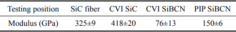
The open porosity and density were measured by Archimedes method. The morphology was observed by the scanning electron microscope (SEM, S4700; Hitachi, Japan). The phase composition was tested by the X-ray diffraction (XRD, Rigaku-D/max-2400; Tokyo, Japan) using Cu Kα (λ = 1.54 Å) radiation. The laser flash method (LFA 427, NETZSCH, Germany) was employed to measure the thermal diffusion (α) and heat capacity (Cp). The thermal conductivity (λ) can be calculated by the following equation: λ = αCpρ, where ρ is the density of sample. The high resistance meter (4339B, Agilent, USA) was conducted to measure the direct-current electrical resistance. The electric resistivity was calculated based on the electrical resistance and dimension of composites. The S-parameters were obtained by the vector network analyzer (VNA, MS4644A, Anritsu, Japan) at 8.2–12.4 GHz (X-band), and the relative complex permittivity εr (εr = ε′ – jε″ where ε′ and ε″ are the real and imaginary part of permittivity, respectively.) at 10 GHz was also acquired. The load–displacement curves were obtained by the three-point bending test with a loading speed of 0.5 mm/min using three 40 mm×5 mm×3 mm test bars. The KIC was evaluated by single-edge notched beam (SENB) test with the loading speed of 0.05 mm/min using three 40 mm×3 mm×5 mm test bars. The modulus of fiber and matrices for SiCf/SiC–SiBCN composites was measured by the nano indentation instrument (Hysitron, TI980, USA), and the maximum load used for nano indentation test is 10 mN. The loading and unloading curve (load with respect to displacement) can be obtained, and the modulus can be calculated based on the unloading curve. The moduli of fiber and matrix for SiC/SiC–SiBCN composites are shown in Table 2.
Table 2 Moduli of fiber and matrix for SiC/SiC–SiBCN composites
3 Results and discussion
3. 1 Microstructure and phase composition of SiCf/SiC–SiBCN composites
The cross-section morphologies of as-fabricated SiCf/SiC and SiCf/SiC–SiBCN composites are shown in Fig. 1. The thickness of BN interface was about 350 nm (Fig. 1(a)), which maybe a little thinner comparing with conventional BN interface thickness (500 nm) in SiCf/SiC composites [20] and would be unfavourable for mechanical properties. The dense CVI SiC matrix can be observed, and the small pores in fiber bundles were filled by SiC. The CVI and PIP SiBCN matrix were mainly located at inter-bundle region. The layered CVI SiBCN deposited via cyclic CVI technology was inserted outside SiC matrix (Figs. 1(b)–1(d)). The porous PIP SiBCN with some microcracks (the orange arrow shown in Fig. 1(b)) and pores (the orange circle shown in Fig. 1(b)) was finally introduced into SiCf preform (Figs. 1(b) and 1(c)). When the SiCf/SiC–SiBCN composites are loaded at high temperatures and oxidizing atmorsphere, the outer SiBCN matrix would be firstly oxidized with massive volume expansion and the borosilicate or SiO2 glass generates according to previous studies [15,16,21]. The cracks can be quickly filled by above glass phase. The inner interphase and fiber would be protected from oxidation. The phase composition of as-fabricated composites is shown in Fig. 2. The characteristic diffraction peaks at 35.59°, 59.98°, 71.78°, and 75.49°, respectively, corresponding to (111), (220), (311), and (222) crystal planes of β-SiC can be observed. The CVI and PIP SiBCN were amorphous according to our previous work [22], and therefore no other diffraction peaks appeared in XRD patterns.

Fig. 1 Cross-section morphologies of SiCf/SiC–SiBCN composites: (a) SiCf/SiC, (b) 1#, (c) 2#, and (d) 3#.
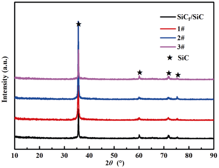
Fig. 2 XRD patterns of as-fabricated composites.
3. 2 Mechanical property and fracture mechanism
The flexural load–displacement curves are shown in Fig. 3. The flexural strength of SiCf/SiC was 325.46±69.78 MPa. As for SiCf/SiC–SiBCN composites, the flexural strength of 1#, 2#, and 3# was 445.69±36.76 MPa, 545.45±29.59 MPa, and 420.75±47.38 MPa, respectively. The curves contained linear and non-linear segments before the stress reached the maximum. Then the curves of both SiCf/SiC and SiCf/SiC–SiBCN composites suddenly declined after the curves passed its peak. The fracture morphologies are exhibited in Fig. 4. The fracture of both SiCf/SiC and SiCf/SiC–SiBCN composites was flat (Figs. 4(a)–4(d)). The interface debonding and fiber pullout with a few micrometers in length can be observed in all composites (Figs. 4(e)–4(h)). The crack deflection at matrix appeared, and the crack propagation path was prolonged (Figs. 4(e)–4(h)). The delamination cracking (Figs. 4(i)–4(l)) was related to the layered matrix structure [23], and the crack propagation energy was consumed. The toughness can be further enhanced.
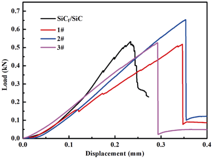
Fig. 3 Three-point bending test load–displacement curves of as-fabricated composites.
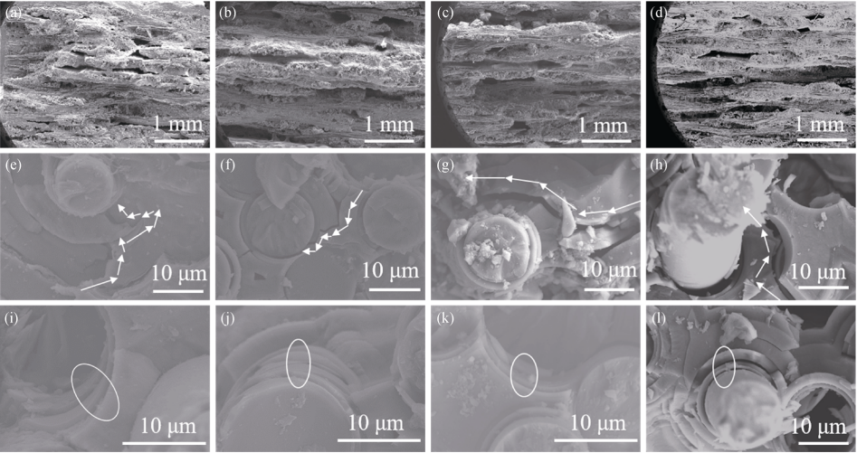
Fig. 4 Fracture morphologies of as-fabricated composites after three-point bending test: (a, e, and i) SiCf/SiC, (b, f, and j) 1#, (c, g, and k) 2#, and (d, h, and l) 3#.
As the composites are loaded, the elastic deformation firstly occurs. With the increase of load, the matrix cracks appear [13,24]. As for SiCf/SiC, the cracks quickly extend in SiC matrix. The sufficient crack deflection at interface area is limited resulting from the strong interface bonding. The fibers quickly rupture and the samples fail. The load–displacment curve suddenly drops. In SiCf/SiC–SiBCN composites, the SiBCN matrix firstly cracks owing to higher strains (originating from the lower modulus according to Table 2). The crack deflection occurs at porous and cracked PIP SiBCN matrix, also at layered CVI SiBCN matrix according to our previous studies [22], which relieves the stress concentration at a crack tip. The crack deflection exists at the interface between PIP and CVI SiBCN matrix (Fig. 5(a)), also at the region between CVI SiBCN and CVI SiC matrix (Figs. 5(b)–5(d)) owing to the modulus difference between them. With the load further improving, the cracks density in SiBCN matrix is saturated, and the SiC matrix begins to play the role of undertaking load at higher stress. The matrix cracks in SiC rapidly initiate and propagate. The interface debonding also occurs in some BN interface regions. Finally, fibers fracture at the top of load–displacement curves, and the composites fail. The conditions for interface debonding are similar according to He and Hutchinson [25] model with the same fiber volume fraction, BN interface thickness and CVI SiC matrix around BN interface for all composites. The interface debonding situation and fiber pullout length are similar for SiCf/SiC and SiCf/SiC–SiBCN composites according to Fig. 4. The difference between SiCf/SiC and SiCf/SiC–SiBCN composites is the load transfer process in multiphase matrix. The crack deflection, occuring in PIP SiBCN, layered CVI SiBCN matrix, also at the interface between PIP and CVI SiBCN matrix, CVI SiBCN and CVI SiC matrix, significantly prolongs the crack propagation path. The flexural strength of SiCf/SiC–SiBCN composites is further improved comparing with SiCf/SiC composites resulting from the crack deflection at the interface of different matrices with different moduli. When the SiCf/SiC–SiBCN composites work at high temperatures and oxidizing environment, the cracks in matrix can be quickly healed by glass phase generating from the oxidation of SiBCN matrix, and the crack deflection further extends the oxygen diffusion path. With the reasonable design of interface and matrix, the BN interface and SiC fiber can be avoided to degenerate by increasing the crack deflection in matrix.
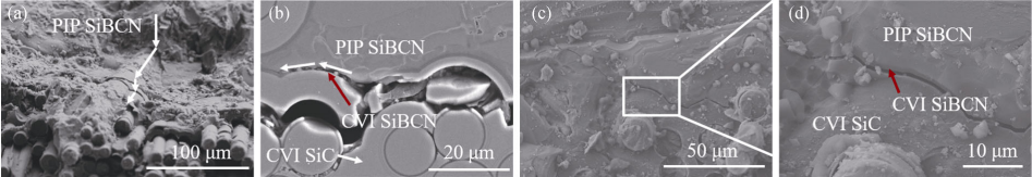
Fig. 5 Crack deflection in multiphase matrix: (a, b) 1#, (c) 2#; (d) the area in the box of (c) ((a, c, and d) are fresh fractures, and (b) is originating from the polished sample at the center area of 1# after three-point bending test).
The load–displacement curves obtained by fracture toughness test are shown in Fig. 6. The fracture toughness (KIC) of SiCf/SiC, 1#, 2#, and 3# was 6.21±2.88, 13.24±0.63, 16.02±0.94, and 12.29±0.96 MPa·m1/2, respectively. The crack propagation route is shown in Fig. 7. In SiCf/SiC composites, the crack deflection was hardly observed and the crack propagation path was almost straight resulting from the strong bonding [26] between fiber and matrix with 350 nm-BN interface (Fig. 7(a)). With regard to SiCf/SiC–SiBCN composites, the fracture toughness was significantly enhanced as a result of the prolonging of crack propagation path (Figs. 7(b)–7(d)). The crack deflection occurred at the interface between PIP SiBCN and CVI SiBCN matrix, as well as between SiC and SiBCN. The crack diffusion energy was consumed and the toughness was improved. The SiCf/SiC–SiBCN composites, possessing excellent flexural strength and fracture toughness, have great potential to be applied as thermo-structural materials.
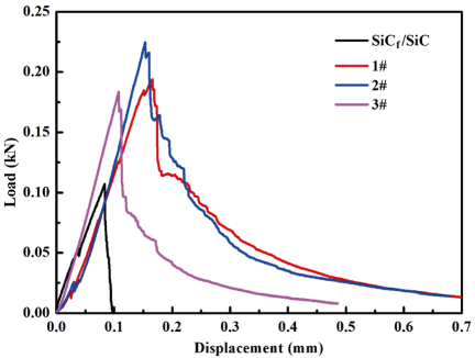
Fig. 6 Fracture toughness test load–displacement curves of as-fabricated composites.
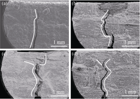
Fig. 7 Crack propagation path via fracture toughness test: (a) SiCf/SiC, (b) 1#, (c) 2#, and (d) 3#.
3. 3 Physical and dielectric properties
The thermal conductivity in the thickness direction as a function of the temperature is shown in Fig. 8(a). The thermal conductivity of SiCf/SiC was 8.89 W·(m·K)-1 at 400℃ . The thermal conductivity of SiCf/SiC–SiBCN declined with the introduction of SiBCN matrix, which can be attributed to the low thermal conductivity of SiBCN ceramic (3 W·(m·K)-1) [6] and the relatively high porosity of the modified composites (Table 1). Heat transfer mode contains radiation, convection, and conduction [27]. The thermal conduction is the main heat transfer mode in solid materials, corresponding to the transfer of a particle’s vibrational energy (or a phonon) to adjacent particles [28]. Hence, the crystallinity has a significant effect on thermal conductivity. The highly crystalline materials usually possess high thermal conductivity [29,30]. As for SiCf/SiC–SiBCN composites, the amorphous SiBCN matrix significantly affected the thermal conductivity of composites. The thermal conductivity (λ) can be theoretically estimated by the Debye equation:
where v is the average phonon velocity and l is the phonon free path. With the increase of temperature, the v is improved. Meanwhile, the lattice vabration is also intensified, and the l is correspondingly decreased. As for SiCf/SiC, the increase of v was dominant comparing with the decline of l from 25 to 400℃ . The vabriation tendency of thermal conductivity from 25 to 400℃ is different from the work by Feng et al. [31,32], which may be ascribed to different stacked ways of SiC fibric, volume fraction of SiC fiber, and interface phase. Then the variation of l had a more significant effect on λ at 400–1200 . The maximum value of ℃ λ was 8.89 W·(m·K)-1 when the temperature was 400℃ , and then it decreased to 7.64 W·(m·K)-1 at 1200℃ . After the introduction of SiBCN ceramic, the rise of v controlled the λ from 25 to 600 . Then, the ℃ λ began to decrease with the reduction of l at 600–1200℃ . The maximum value of λ was 3.92, 7.18, and 5.35 W·(m·K)-1 at 600 , ℃ corresponding to 1#, 2#, and 3#, respectively. According to the results of Zhang et al. [18], the atomic rearrangement occurs when the temperature is above preparation temperature of SiBCN. Some by-product gases generate and the volume shrinks. It means the porosity of composites may increase. This condition has harmful effect on thermal conductivity when the temperature is above 1000℃ .The electric resistance at room temperature was also measured and the electric resistivity is shown in Fig. 8(b). The value of electric resistivity for SiCf/SiC was 1.9×10³ Ω·m[19]. As for 1#, the value of electric resistivity was 9.04×10³ Ω·m because the electric resistivity of PIP SiBCN matrix was high. With the increase of CVI SiBCN matrix, the electric resistivity decreased, which can be attributed to the abundant free carbon phase in CVI SiBCN [22]. The electric resistivity of 2# and 3# was 5.09×10³ and 1.53×10³ Ω·m, respectively.
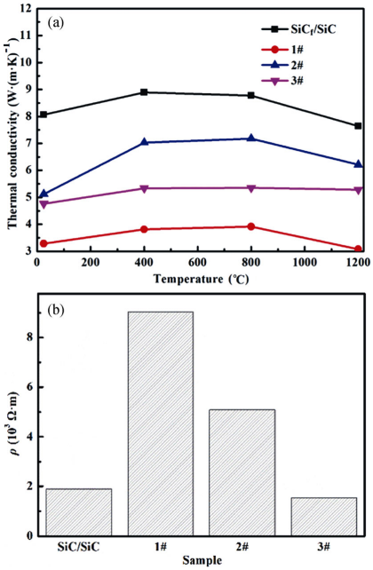
Fig. 8 (a) Thermal conductivity and (b) electric resistivity of as-fabricated composites.
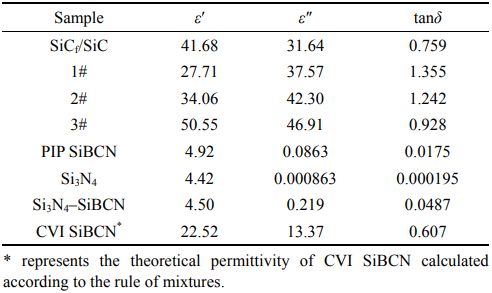
The dielectric property is estimated by the relative complex permittivity, and the tunable dielectric property of as-fabricated SiCf/SiC–SiBCN is shown in Table 3. The value of ε′ was 41.68, 27.71, 34.06, and 50.55, and the ε″ was 31.64, 37.57, 42.3, and 46.91 at 10 GHz for SiCf/SiC, 1#, 2#, and 3#, respectively. The loss tangent (tanδ = ε″/ε′) was 0.759, 1.355, 1.242, and 0.928, respectively. The intrinsic permittivity of SiBCN matrix was also tested and shown in Table 3. The ε′ and ε″ of PIP SiBCN were 4.92 and 0.0863 at 10 GHz, respectively. The low ε″ means poor EMW absorbing characteristic and good impendace matching ability of PIP SiBCN matrix. In order to obtain the permittivity of CVI SiBCN, the Si3N4 substrate with the wave-transparent characteristic was placed into the CVI furnace. According to the deposition processing of SiCf/SiC–SiBCN composites, the SiBCN was deposited on Si3N4 substrate. The ε′ and ε″ of Si3N4 were 4.42 and 0.000863 at 10 GHz, respectively. The ε′ and ε″ of Si3N4–SiBCN composite ceramics with about 8 vol% of CVI SiBCN were 4.50 and 0.219 at 10 GHz, respectively. It indicated the introduction of SiBCN and the formation of interface polarization [33] at the Si3N4/SiBCN interface area significantly enhanced the dielectric property. The ε′ and ε″ of CVI SiBCN were 22.52 and 13.67 calculated according to the rule of mixtures [34]. The CVI SiBCN with high permittivity (thanks to its abandant free carbon) had excellent EMW attenuation property comparing with that of PIP SiBCN. The 1#, with higher content of PIP SiBCN matrix, possessed the lowest ε′ and ε″ in SiCf/SiC–SiBCN composites. With the increase of CVI SiBCN content, the value of permittivity rised. The ε′ and ε″ of 2# increased 0.229 times and 0.126 times comparing with that of 1#, respectively. The ε′ and ε″ of 3# increased 0.824 times and 0.249 times comparing with that of 1#, respectively. The increment of ε″ was lower than that of ε′, and the tanδ of 2# and 3# correspondingly reduced. Additionally, the heterogeneous interface, SiC/SiBCN (CVI), and SiBCN (CVI)/SiBCN (PIP), formed with the introduction of SiBCN matrix. The polarization phenomenon was enhanced owing to the dielectric property difference between different matrices in the external alternating electromagnetic fields [35].
Table 3 Dielectric property of as-fabricated composites at 10 GHz
The EM shielding effectiveness was calculated using scattering parameters (S-parameters: S11, S12, S21, and S22), which was obtained by VNA. The SET consists of reflection shielding effectiveness (SER), absorption shielding effectiveness (SEA), and multiple reflection shielding effectiveness (SEM). When the SET > 15 dB, the SEM can be ignored. The SET is described as follows:
SET = SER + SEA (2)
where SER and SEA can be calculated using the reflection coefficient (R) and the transmission coefficient (T) by the following equations:
SER =-10log(1-R) (3)
SEA =-10log[ T/(1-R)] (4)
where R and T can be expressed by the following equations [36,37]:
R = |S11|²=|S22|² (5)
T=|S12|²=|S21|² (6)
The calculated shielding effectiveness is shown in Fig. 9. The SET of SiCf/SiC, 1#, 2#, and 3# was 23.82, 26.08, 26.23, and 30.01 dB at 10 GHz, respectively. The SER of SiCf/SiC, 1#, 2#, and 3# was 8.46, 6.58, 7.23, and 7.86 dB, respectively. The corresponding SEA was 15.36, 19.50, 19.00, and 22.15 dB, respectively. The SEA was remarkably greater than SER, and it indicated that the EM shielding property of both SiCf/SiC and SiCf/SiC–SiBCN composites was mainly dependent on EMW absorption. It is worthy noting that the EM shielding effectiveness of 3#, with the value of 30.01, was the best among the modified composites. With the introduction of impedance-matched PIP SiBCN matrix, the SER of SiCf/SiC–SiBCN composites decreased comparing with that of SiCf/SiC. It meant less EMW was reflected on the surface of samples and more EMW entered the composites. With the enhanced dielectric property of SiCf/SiC–SiBCN composites, the SER gradually improved. The R and absorption coefficient (A) at 10 GHz were calculated to further analyze the EM properties of composites. For 1#, 2#, and 3#, the value of R was 0.78, 0.81, and 0.84, and the value of A was 0.22, 0.19, and 0.16, respectively. The R of 3# is the highest and the A is the lowest. It indicated that more and more EMW was reflected when it reached the surface of as-fabricated composites resulting from the huge differences between air and as-fabricated composites with increased CVI SiBCN. Deriving from the effective attenuation of EMW at the interface between the successive layers of CVI SiBCN matrix, the 3# had the highest value of SEA among the SiCf/SiC–SiBCN composites [22]. The SiCf/SiC–SiBCN composites, with tunable dielectric and EM shielding effectiveness, can act as outstanding EM shielding materials.
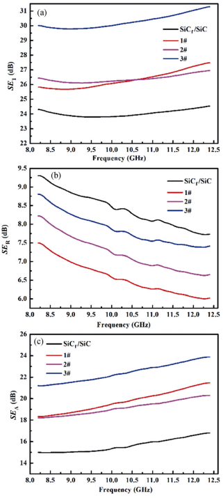
Fig. 9 Shielding effectiveness of as-fabricated composites: (a) SET, (b) SER, and (c) SEA.
4 Conclusions
The SiCf/SiC–SiBCN composites were successfully prepared via CVI combined with PIP technologies. The following conclusions can be summarized:
1) The stronger interface bonding with the thickness of BN interface about 350 nm was designed, and the internal pores of the fiber bundles were filled by CVI SiC matrix. The amorphous CVI SiBCN and PIP SiBCN matrix were orderly introduced outside the SiC matrix.
2) The flexural strength and fracture toughness of SiCf/SiC–SiBCN composites, containing 15 vol% CVI SiBCN matrix and 8 vol% PIP SiBCN matrix, were 545.45±29.59 MPa and 16.02±0.94 MPa·m1/2, respectively. The crack propagation path was further increased in the layered CVI SiBCN matrix and cracked PIP SiBCN matrix, additionally at the interface area between CVI and PIP SiBCN matrix, CVI SiBCN and SiC matrix. The crack propagation energy was severely attenuated, and enhanced mechanical properties can be obtained comparing with SiCf/SiC composites.
3) Resulting from the higher open porosity and the introduction of amorphous SiBCN matrix with low thermal conductivity, the thermal conductivity of SiCf/SiC–SiBCN composites in the thickness direction was lower than SiCf/SiC composites. Owing to the abundant free carbon in CVI SiBCN, the electrical resistivity decreased with the increased content of CVI SiBCN matrix.
4) The EM shielding property of SiCf/SiC–SiBCN composites was mainly dependent on SEA. The SET, SER, and SEA of 3# were 30.01, 7.86, and 22.15 dB, respectively, which shows that the SiCf/SiC–SiBCN composites are the excellent candidate to act as structural and functional composites.
References: omitted
Declaration: This article is provided by CERADIR™ users or obtained from Internet, the content does not represent the position of CERADIR™. We are not responsible for the authenticity/accuracy of the article, especially the effects of the products concerned. This article is for study only, it does not constitute any investment or application advice. For reprinting, please contact the original author. If it involves the copyright and/or other issues, please contact us and we will deal with it asap! CERADIR™ has the interpretation of this declaration.