Abstract: Fiber damage and uniform interphase preparation are the main challenges in conventional short fiber reinforced ceramic matrix composites. In this work, we develop a novel processing route in fabrication of short carbon fiber reinforced ZrB2–SiC composites (Csf/ZrB2–SiC) overcoming the above two issues. At first, Csf preforms with oriented designation and uniform PyC/SiC interphase are fabricated via direct ink writing (DIW) of short carbon fiber paste followed by chemical vapor infiltration. After that, ZrB2 and SiC are introduced into the preforms by slurry impregnation and reactive melt infiltration, respectively. Microstructure evolution and optimization of the composites during fabrication are investigated in detail. The as-fabricated Csf/ZrB2–SiC composites have a bulk density of 2.47 g/cm³, with uniform weak interphase and without serious fiber damage. Consequently, non-brittle fracture occurs in the Csf/ZrB2–SiC composites with widespread toughening mechanisms such as crack deflection and bridging, interphase debonding, and fiber pull-out. This work provides a new opportunity to the material design and selection of short fiber reinforced composites.
Keywords: short fiber reinforced composites; ultra-high temperature ceramics (UHTCs); interphase; orientation
1 Introduction
Ultra-high temperature ceramics (UHTCs) are endowed with extremely high melting point (over 3000 ℃), good mechanical properties, and excellent chemical stability at elevated temperatures [1]. These unique combinations of properties make them leading candidates for extremely environmental applications, such as nozzles, leading edges, and engine components of hypersonic aircraft. However, the intrinsic brittleness and poor thermal shock resistance of UHTCs limit their wide applications [2]. With carbon fiber as reinforcements, it can effectively overcome the above issues of UHTCs. In the past few years, extensive research has been carried out on continuous carbon fiber reinforced UHTC matrix composites (Cf/UHTCs), including design, processing, and properties [3–8], etc. Compared with continuous fibers, short carbon fiber reinforced UHTC composites (Csf/UHTCs) show more superior designability, and are easier to get a high UHTCs content in the composites [9,10]. Accordingly, Csf/UHTCs provide great potential for high-performance UHTCs composites.
Generally, Csf/UHTCs are prepared by ceramic processing, such as hot pressing [11–13], spark plasma sintering [14–16], pressureless sintering, and reactive melt infiltration (RMI). For the Csf/UHTCs composites fabricated by these conventional methods, there are two main bottlenecks. On the one hand, it is difficult to prepare uniform interphase on the surface of the fibers in the above-mentioned processing routes [17]. A weakly bonded interphase can not only improve the toughness of the material through residual stress relaxation and interfacial debonding but also protect the fibers [18,19]. On the other hand, short carbon fibers are damaged significantly during ceramic processing, such as ball milling and pressure-assisted sintering [20]. Consequently, the effect of strengthening and toughening is very limited in conventional Csf/UHTCs composites in which the fibers are randomly distributed [21–24]. As a result, only those fibers perpendicular to the direction of cracks can hinder the crack propagation through fiber pull-out and bridging when Csf/UHTCs break [25]. Recently, direct ink writing (DIW) method, a kind of 3D-printing technology, is used to prepare composites with oriented short carbon fibers [12,26,27]. Due to the ceramic powder is mixed in the inks, intact interphase is difficult to deposite on the fiber surface [28].
In this work, we develop a novel processing route in fabrication of short carbon fiber reinforced ZrB2–SiC composites (Csf/ZrB2–SiC) overcoming the above mentioned two issues. At first, Csf preforms with oriented designation and uniform PyC/SiC interphase are fabricated via DIW of short carbon fiber inks followed by chemical vapor infiltration. After that, ZrB2 and SiC are introduced into the preforms by slurry impregnation and reactive melt infiltration, respectively. Based on the fine structure design and processing control, the fibers and uniform weak interphase are well protected during fabrication. A non-brittle fracture is achieved in the Csf/ZrB2–SiC composites accordingly. Microstructure evolution and optimization of the composites during fabrication are investigated in detail.
2 Experimental
2. 1 Material
Commercially available ZrB2 (purity > 99%, particle size: 1–3 µm; Shanghai Yaotian New Material Technology, Shanghai, China) and short carbon fibers (M40, average length: 200–500 μm; Toray Industries, Tokyo, Japan) were used as the raw materials. Polyvinyl pyrrolidone (PVP, Mw = 1,300,000, purity: 99%; Sinopharm Chemical Reagent, Adamas, Shanghai, China), polyvinyl butyral (PVB, Mw = 90,000–120,000, purity: 99%; Aladdin, Shanghai, China), and methylcellulose (MC, purity: 0.4 Pa·s; Adamas, Shanghai, China) were used as the binder, dispersant for ZrB2, and dispersant for Csf, respectively.
2. 2 Preparation of Csf paste and preforms
The preparation of Csf paste included three steps: (I) Csf and MC (1 wt% of short carbon fibers) were first added to deionized water to prepare uniformly dispersed fiber suspension by ultrasonication. (II) PVP (constant weight ratio of PVP:Csf =1:3) was added into ethanol as binder by magnetic stirring. (III) The above two solutions obtained by (I) and (II) were mixed by magnetic stirring in water bath at ~50 ℃. The Csf paste was obtained after evaporation of ethanol and deionized water until the fiber concentration achieving ~70% and the short carbon fiber suspension became toothpaste-like.
After that, Csf paste was transferred into a print nozzle and installed in a 3D printer (Regenovo 3D bioprinter V2.0, Regenovo Biotechnology Co., Ltd., Shanghai, China). Csf preforms were printed using a nozzle with inner diameter of 0.84 mm driven by nitrogen at a pressure of 0–0.6 MPa. The speed of the nozzle moving in the x-axis and y-axis directions was set to 0–5 mm/s and the distance between filaments was set to 0.5 mm. The dimensions of the preforms were set to 40 mm × 30 mm × 5 mm. The Csf preforms were printed layer by layer under the control of computer with a designed route. When the first layer was completed on a glass, the next layer would be printed after rotating 90° in turn. The Csf preforms were obtained after about 10 layers of printing followed by dryness at 55 ℃ for 24 h.
2. 3 Fabrication of Csf/ZrB2–SiC composites
The Csf preforms were firstly heat-treated to remove the organics in a carbon-tube furnace at 1200 ℃ under Ar atmosphere. PyC/SiC interphase was then deposited on the fiber surface via chemical vapor infiltration (CVI) successively. The obtained Csf@PyC/SiC preforms had a porosity of ~80 vol%.
After that, ZrB2 and SiC were introduced into the Csf@PyC/SiC preforms by slurry impregnation (SI) and RMI, respectively. ZrB2 slurry (60 wt%) with phenolic resin, PVB, and pore former were obtained by ball-milling in a polyethylene bottle using SiC balls and ethanol as the media. Then the ZrB2 slurry was introduced into the Csf@PyC/SiC preforms by vacuum impregnation and then heat-treated at 900 ℃ in Ar atmosphere so that Csf@ZrB2–C porous preforms were obtained. Finally, Si melt was infiltrated into the Csf@ZrB2–C porous preforms under vacuum at 1490 ℃ and Csf/ZrB2–SiC composites were formed. The schematic of the fabrication process is shown in Fig. 1.

Fig. 1 Schematic diagram of the procedure for Csf/ZrB2–SiC composite fabrication.
2. 4 Characterizations
The rheological behavior of the ink was determined by a stress-controlled rheometer (Universal Stress Rheometer SR5, Rheometric Scientific, USA). Microstructure of the Csf preforms and composites were observed using a field emission scanning electron microscope (FESEM; Hitachi SU8220, Tokyo, Japan) along with energy-dispersive spectrometry (EDS; Inca energy, Oxford, UK) for elemental analysis. Phase composition was analyzed by an X-ray diffractometer (XRD; D8 Discover Davanci, Bruker Vorporation, Germany). Pore size distribution of the porous preforms was determined by mercury porosimeter (AutoPoreIV9510, Micromeritics Instrument Corporation, Shanghai, China). Density and open porosity of the composites were determined by the Archimedes method using distilled water as media. Calculation process is as follows:
ρ=M1×ρ0/(M3-M2) (1)
ρ=(M3-M1)/(M3-M2)×100% (2)
where ρ and P are the bulk density and open porosity of the composites, respectively. ρ0 is the density of deionized water at room temperature, M1 is the dry weight of the sample, M2 is the floating weight of the sample saturated with water, and M3 is the weight of the sample saturated with water in the air.
Orientation parameter (fp) similar to “Hermans’ orientation parameter” [29] of the fibers in the composites was determined by the equations below [30]:
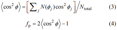
where Φ is the angle between the fibers and x-axis identified by image analysis. The short carbon fibers are perfectly oriented in the composite when fp tends to 1, and randomly distributed when fp tends to 0. Fracture behavior of the composites was measured by a single-edge-notched beam (SENB) method with a specimen size of 30 mm × 6 mm × 3 mm, notch length of 3 mm, notch depth of 1.5 mm, crosshead speed of 0.5 mm/min, and support span of 24 mm.
3 Results and discussion
3. 1 Preparation and optimization of Csf paste & preforms
The good rheology of the paste is critical for successive 3D-printing. And uniform dispersion of Csf is the premise for good rheology. MC is a nonionic surfactant with excellent wettability, dispersibility, and adhesion properties [31], which can be absorbed on the surface of carbon fibers and get a good colloidal stability in an aqueous solution as shown in Fig. 2(a) [32]. Without the addition of MC, the short carbon fibers will get together and agglomerate under the surface tension, as shown in Fig. 2(c). The introduction of MC can form a colloid layer surrounding the fibers and separate them from each other (Fig. 2(d)), improving the stability of Csf in the suspension effectively. On the other hand, PVP has the same π–π bond like graphene, and it can be physically absorbed on the surface of Csf in polar solution, i.e., aqueous or ethanol [33,34]. Therefore, PVP addition can further improve the dispersion and stability of Csf suspension. The slurry becomes a pseudoplastic fluid with shear thinning. As a pseudoplastic fluid, when the slurry flows in the cylindrical nozzle, the shear force decreases nonlinearly along the radial direction [35]. The slurry and the superficial fibers will be subjected to shear force from the nozzle wall while the inner slurry and fibers will only suffer a limited shear force from the superficial slurry. As a result, the superficial slurry flows faster than the inside, forming the shearing force which makes the superficial fibers quickly rotate to the flowing direction. Because the nozzle is long enough, the internal fibers gradually turn to the flowing direction as shown in Fig. 2(b). As a result, most carbon fibers are well oriented.
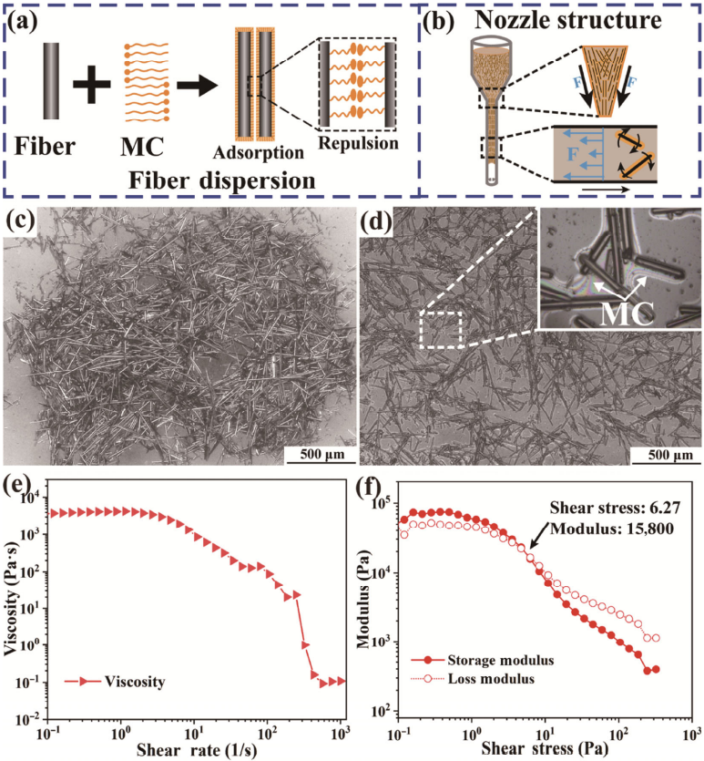
Fig. 2 (a) Schematic diagram for MC absorbed on the carbon fiber surface and dispersing the carbon fibers; (b) shear force distribution and fiber orientation process in the nozzle structure; (c) optical image of Csf agglomeration; (d) optical image of Csf with good dispersion; (e) apparent viscosity of Csf paste as a function of shear rate; (f) storage modulus and loss modulus of Csf paste as a function of shear stress.
With the evaporation of deionized water and ethanol, the viscosity of the suspension rose rapidly. The final Csf paste exhibited obvious shear-thinning effect and suitable viscoelasticity for DIW. Under shearing force, the short carbon fibers in the suspension aligned along the flow direction, which reduced the resistance of suspension flowing. Figure 2(e) presents the viscosity of the Csf paste, which shows an obvious shear-thinning phenomenon as discussed above. Figure 2(f) suggests that when shear stress is higher than yield stress (6.27 Pa), the storage modulus of the Csf paste is lower than the loss modulus, indicating a viscous fluid, which is good for the Csf paste flowing through the nozzle. As the Csf paste is extruded from the nozzle, shear stress reduces dramatically. When the shear stress is lower than the yield stress, the storage modulus (104–105 Pa) becomes higher than the loss modulus in turn, indicating an elastic fluid, which is beneficial to maintain the shape of the filaments and Csf preforms after printing.
Figure 3(a) shows the DIW fabrication of Csf preforms. When the obtained Csf preforms were dried, MC molecules formed a gel based on hydrogen bonds, preventing the shrinkage of PVP molecules. As a result, the volume shrinkage of Csf preforms is as low as 5.6 vol%. Figure 3(b) shows that the shape of the filaments is stable and the fibers are closely connected by organics and oriented obviously. After organics were removed by heat-treatment, the oriented Csf were exposed completely and ready for interphase deposition (Fig. 3(c)). The content of Csf in the as-fabricated preforms is ~21 vol%.
To characterize the shear stress-induced orientation of the Csf, the angles between Csf and main axis at different districts were measured, as shown in Fig. 3(c). Figure 3(d) gives the statistic angle distribution of Csf along x-axis after more than 400 Csf were counted, which shows that the angles are mainly distributed between −30° and 30°, especially between −10° and 10°, indicating the Csf are well aligned. The orientation parameter is calculated according to Eqs. (3) and (4). The calculated orientation parameter fp is 0.84, which further confirms the good orientation of Csf in this work.
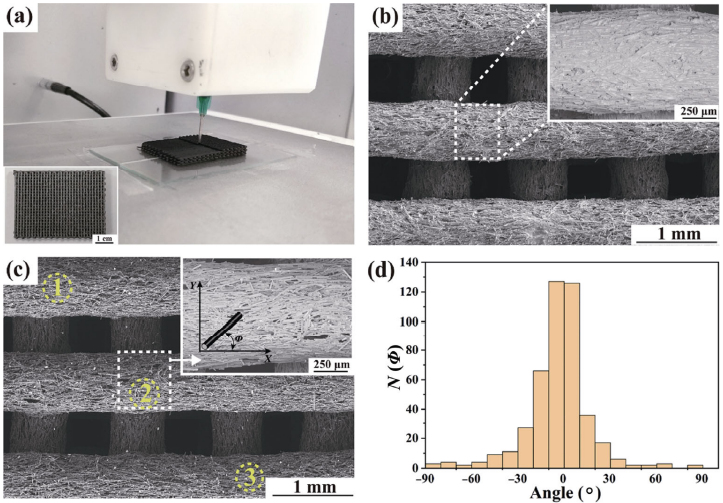
Fig. 3 (a) Optical image of Csf preform fabrication by DIW, (b) SEM images of Csf preform before heat-treatment, (c) SEM images of Csf preform after heat-treatment, and (d) statistic angle distribution of Csf.
3. 2 Fabrication and microstructure evolution of Csf/ZrB2–SiC composites
As described above, PyC/SiC interphase was deposited on the surface of Csf by CVI after organics removement. As shown in Fig. 4, a uniform and intact interphase is obtained, where the PyC is around 300 nm in thickness and the SiC layer is around 3 μm. The deposition of PyC/SiC interphase also makes the Csf connect to each other and endows the Csf@PyC/SiC preforms rigidity. The thin PyC interface does not close the pores in the filaments and the subsequent SiC deposition is not affected (Fig. 4(a)). However, after deposition of the thick SiC layer (Figs. 4(b) and 4(c)), most of the pores in the Csf filaments are closed, which adversely affects the subsequent densification process of the composites.
Fig. 4 SEM images and EDS analysis of Csf preform after PyC/SiC interphase deposition: (a) surface after PyC interface, (b) surface after SiC interphase, (c) section after SiC interphase deposition, (d) EDS spectrum of Spot 1, (e) EDS spectrum of Spot 2, and (f) line scan spectrum in (c).
Densification of the Csf@PyC/SiC preforms includes two steps. At first, porous ZrB2–C is introduced into the preforms by slurry impregnation, and then the preforms are further densified by Si infiltration (Fig. 1). After PyC/SiC deposition, the main pores in the preforms are mainly located among Csf filaments with a size of hundreds of microns. Therefore, ZrB2–C can be effectively introduced into the preforms by slurry impregnation. Figure 5 shows the SEM images and pore size distribution of the porous Csf@ZrB2–C. After slurry impregnation, the introduced ZrB2–C is mainly located among the Csf filaments, but also enters the fiber bundles as shown in Fig. 5(a). The Csf and PyC/SiC interphase remain intact without obvious damage occurred (Fig. 5(b)). The microstructure shows that the introduced ZrB2–C is uniformly distributed with micro-nano pores embedded, which can provide a channel for Si infiltration (Fig. 5(c)).
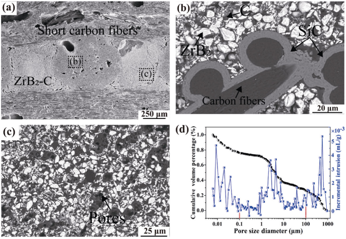
Fig. 5 SEM images and pore size distribution of porous Csf@ZrB2–C: (a) low magnification of the Csf@ZrB2–C, (b) SEM image of the fiber bundle location, (c) SEM image of the matrix, and (d) cumulative volume percentage and incremental intrusion vs pore size diameter of the Csf@ZrB2–C.
The obtained Csf@ZrB2–C has an open porosity of ~20 vol%. Based on pore size distribution, they can be divided into three types, which are mainly caused by two different reasons (Fig. 5(d)). The nano-pores with a diameter of less than 0.1 μm and micro-pores with a diameter between 0.1 and 100 μm are mainly caused by pore former removement during heat-treatment. The volume of these two types of pores is accounted for 24 and 51 vol%. A few large pores (> 100 μm, ~25 vol%) are also presented, which are mainly located on the surface of preforms and caused by slurry outlet flowing during solidification after slurry impregnation. It is expected that such micro-nano multi-level pores can promote the kinetics of Si infiltration to get a dense matrix [36]. Besides open pores, some closed pores also exist in the Csf@ZrB2–C. The closed pores mainly originate from the DIW process, during which air enters into the paste and is difficult to remove completely. As a result, pores are left inside the filaments, which are partly closed after PyC/SiC deposition.
The Csf/ZrB2–SiC composites are finally obtained after Si infiltration, where the Si melt reacted with carbon to form SiC based on the chemical reaction as Eq. (5)
C + Si = SiC (5)
Thermodynamic calculation by HSC chemistry version 6.0 (Outokumpu Research Oy, Pori, Finland) indicates that Gibbs free energy change (ΔG) of Eq. (5) is about −55.19 kJ/mol at 1490 ℃. The as-fabricated Csf/ZrB2–SiC composites have a density of ~2.47 g/cm³ with a porosity of around 18.8%. The volume fractions of the ZrB2 and SiC are ~29.4 and ~30.7 vol%, respectively. The high porosity of the composite is partially due to the large pores which are mainly located on the surface of the Csf@ZrB2–C preforms and caused by slurry outlet flowing during solidification after slurry impregnation. Some of these large pores were filled with molten Si (Fig. 6(a)) while still many were not and remained in the final composite between the filaments. In addition, some pores closed by thick silicon carbide cannot be infiltrated by Si and stay as closed pores in the filaments (Fig. 6(b)). As a result, the final composite has a high porosity. XRD pattern shows the phase composition of the obtained Csf/ZrB2–SiC (Fig. 7). In addition to C, ZrB2, and SiC, Si residuals are also detected, which is very common in Si infiltrated composites. The Si residuals are mainly located among the Csf filaments (Fig. 6(a)) and generally have a large size (> 100 μm). During RMI, Si cannot fully fill in the large pores and completely react with the carbon in the preform, leaving pores or Si residuals in the final composite. Therefore, Si residuals might be reduced by decreasing the large pores in the Csf@ZrB2–C preforms. From the section of the fiber bundle, it can be found that the carbon fibers and PyC/SiC interphase are well protected without obvious erosion (Fig. 6(b)). It can be found that ZrB2 grains surrounded with Si residuals grow up remarkably due to the effect of liquid-phase assisted mass transfer (Fig. 6(c)).
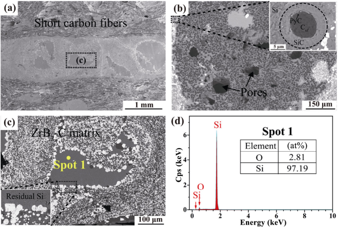
Fig. 6 SEM images and EDS analysis of Csf/ZrB2–SiC composites: (a) polished surface, (b) section of fiber bundle, (c) high magnification image in (a), and (d) EDS spectrum of Spot 1.
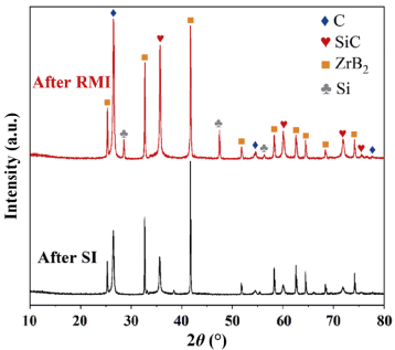
Fig. 7 XRD patterns of Csf@ZrB2–C after SI and Csf/ZrB2–SiC composites after RMI.
3. 3 Fracture behavior of Csf/ZrB2–SiC composites
The fracture behavior of the Csf/ZrB2–SiC composites was analyzed by bending test. Figure 8(a) shows the crack propagation and fracture surface of the Csf/ZrB2–SiC composites after bending test. The composites perform obvious non-brittle fracture characteristics. The sample were tilted during machining, resulting in more fibers at the upper fiber bundle regions and less fibers at the lower fiber bundle regions in Fig. 8(a). As the crack passes through the composite, the more fibers there are, the more crack deflects. As a result, the crack deflection is less at the lower fiber bundle regions in Fig. 8(a). As discussed above, the carbon fibers and PyC/SiC interphase are well protected without obvious erosion in the as-fabricated Csf/ZrB2–SiC composites. Csf are debonded from the weak PyC interphase when cracks propagate to the carbon fibers, and no direct broken fibers are observed. Some Csf slip from the composites and form crack bridging or fiber pull-out, which promote the cracks deflecting along the Csf oriented direction, as shown in Fig. 8(b). On the fracture surface of the composites (Figs. 8(c) and 8(d)), widespread toughening mechanisms such as crack deflection and bridging, interphase debonding, and fiber pull-out can also be observed clearly. The toughening mechanisms in the as-fabricated Csf/ZrB2–SiC composites mainly resulted from the well-protected Csf and weak interphase, which consumes the crack propagation energy remarkably. This work provides a new opportunity to the material design and selection of short fiber reinforced UHTC composites.
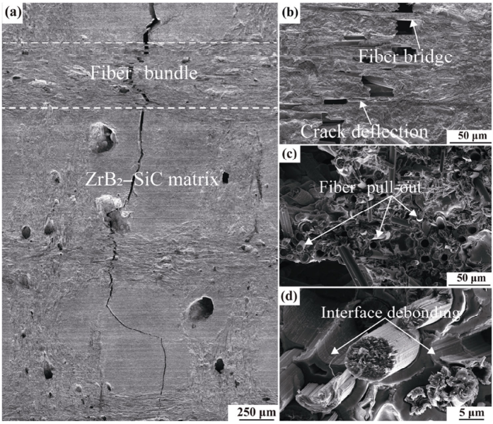
Fig. 8 Typical crack propagation behavior and fracture surface of the Csf/ZrB2–SiC composite after bending test: (a) crack propagation path, (b) magnification of crack propagation path, (c) fracture surface, and (d) magnification of fracture surface.
4 Conclusions
In this work, a novel processing route that combined with DIW and RMI was developed to fabricate Csf/ZrB2–SiC composites. The rheology of the Csf paste, microstructure evolution, and toughening mechanisms of the composites were analyzed and discussed. At first, Csf paste suitable for DIW was obtained with the help of the binder and dispersant, showing an obvious shear-thinning behavior. The Csf were well oriented by the shearing force from the nozzle during DIW, with an orientation parameter fp ≈ 0.84. Based on the fine structure design and processing control, the fibers and uniform PyC/SiC interphase are well protected during fabrication. The as-fabricated Csf/ZrB2–SiC composites have a density of ~2.47 g/cm³. Beneficial to the weak bonding between fibers and matrix, non-brittle fracture is achieved in the Csf/ZrB2–SiC composites accordingly, with widespread toughening mechanisms such as crack deflection and bridging, interphase debonding, and fiber pull-out. Although further optimization of the fabrication processing is still required, this work provides a new opportunity to the material design and selection of short fiber reinforced composites.
References: omitted
Declaration: This article is provided by CERADIR™ users or obtained from Internet, the content does not represent the position of CERADIR™. We are not responsible for the authenticity/accuracy of the article, especially the effects of the products concerned. This article is for study only, it does not constitute any investment or application advice. For reprinting, please contact the original author. If it involves the copyright and/or other issues, please contact us and we will deal with it asap! CERADIR™ has the interpretation of this declaration.