Abstract: To further improve the oxidation resistance of polymer derived ceramic (PDC) composites in harsh environments, Cf/SiC/SiHfBOC composites were prepared by chemical vapor infiltration (CVI) and precursor impregnation pyrolysis (PIP) methods. The weight retention change, mechanical properties, and microstructure of Cf/SiC/SiHfBOC before and after oxidation in air were studied in details. Microscopic analyses showed that only the interface between the ceramics and fibers was oxidized to some extent, and hafnium had been enriched on the composite surface after oxidizing at different temperature. The main oxidation products of Cf/SiC/SiHfBOC composites were HfO2 and HfSiO4 after oxidation at 1500 °C for 60 min. Moreover, the weight retention ratio and compressive strength of the Cf/SiC/SiHfBOC composites are 83.97% and 23.88±3.11 MPa, respectively. It indicates that the Cf/SiC/SiHfBOC composites should be promising to be used for a short time in the oxidation environment at 1500 °C.
Keywords: Cf/SiC/SiHfBOC composites; precursor infiltration pyrolysis (PIP) method; mechanical properties; high-temperature oxidation resistance
1 Introduction
The requirements of thermal protection materials such as lightweight, strengthening toughening, and oxidation resistance are increasing in the combustion chamber and tail nozzle of aerospace vehicles [1–3]. The thermal protection materials represented by ceramic thermal insulation tiles are difficult to meet the requirements of increasing the service environment temperature of hypersonic spacecraft [4–7]. In addition, ceramic matrix composites have attracted much attention due to their excellent thermal stability and high compressive strength [8]. However, the intrinsic brittleness and poor thermal shock resistance of ultra-high temperature seriously restrict the wide application of ceramic thermal protection materials [9,10]. The high-performance silicon-based precursor ceramics have an excellent thermodynamic stability. SiOC-based precursor ceramics have been applied in the hot end components of aerospace vehicles.However, the strong carbothermal reduction occurs in the environment above 1300 ℃, which seriously restricts the development of silicon-based precursor ceramics. It is found that the high-temperature stability of SiOC ceramics can be effectively improved by doping boron, nitrogen, zirconium, hafnium, and other elements. At present, a variety of precursor ceramics have been synthesized, such as SiBOC [11], SiZrOC [12], SiHfOC [12], SiAlOC [13], SiBCN [14], SiHfBOC [3], and SiBCNZr [14].
Continuous carbon fiber (or carbon fiber perform) reinforced ceramic matrix composites have the excellent properties, such as low density [15], high toughness [16], high strength, and high reusability [17], especially the toughening property [18], which help to solve the inherent brittleness of ceramic materials [19]. It not only improves the thermal shock resistance of ceramic materials, but also maintains the inherent high-temperature stability and low thermal expansion coefficient of ceramic materials [8]. Therefore, continuous carbon fiber reinforced ceramic matrix composites have been widely studied in recent years.
However, due to the low reaction activity of carbon fiber and the damage of carbon fiber in a high-temperature oxidation environment, the interface bonding performance between continuous fiber-reinforced phase and the ceramic matrix will be reduced, and the excellent characteristics of continuous carbon fiber cannot be brought into full play. The coating will reduce the area of carbon fiber exposed to oxygen atmosphere, thus improving the oxidation resistance of the composites Therefore, chemical vapor deposition (CVD), chemical vapor infiltration (CVI), and hydrothermal methods can be used to prepare coatings on carbon fiber surface [1,17,20]. The types of coatings include C coating [21], BN coating [22], SiC coating [23,38], etc. These coatings not only change the surface roughness of carbon fiber but also improve the interface bonding performance between ceramic matrix and carbon fiber reinforcement. In the process of ceramic pyrolysis, the coating could protect carbon fibers by inhibiting the surface damage of carbon fiber either. The oxidation temperatures of C coating and BN coating are 400 and 800 ℃, respectively. However, the SiC coating has an excellent oxidation resistance below 1600 ℃, mainly because the formed SiO2 can be used to prevent further oxidation and ablation. Generally when the oxidation temperature exceeds 1600 ℃, the volatility of SiO2 increases rapidly, and the gaseous product SiO escapes, resulting in the failure of SiO2. In addition, SiC coating has good physical and chemical compatibility with carbon fiber. At the same time, it is also the most studied and mature material. Thus, it is an ideal oxidation resistance and ablation resistance coating material [24,30,38].
The precursor solution of SiHfBOC had been prepared in the previous work. Therefore, in this article, SiC coating was prepared on the surface of carbon fiber by CVI, and then SiHfBOC precursor sol was ultrasonically impregnated into the framework of carbon fiber preform coated with SiC coating by precursor infiltration pyrolysis (PIP). After solvothermal reaction and high-temperature pyrolysis, Cf/SiC/SiHfBOC ceramic matrix composites were fabricated. Their micromorphology and phase evolution were analyzed. Additionally, the strengthening–toughening mechanism and oxidation resistance of Cf/SiC/SiHfBOC ceramic matrix composites were also evaluated. Compared with traditional composites, Cf/SiC/SiHfBOC composites were prepared with lower PIP cycle times, and have excellent oxidation resistance and mechanical property.
2 Experimental
2. 1 Materials
The commercially available methyltriethoxysilane (MTES, CH3Si(OCH2CH3)3, 99% purity; purchased from Aladdin Co., Ltd., Shanghai, China), boric acid (B(OH)3, 98% purity; purchased from Harbin Chemical Reagent Factory Co., Ltd., Harbin, China), tetrachloride hafnium (HfCl4, 99.5% purity; purchased from Aladdin Co., Ltd., Shanghai, China), T700 PAN-based carbon fibers (Cf preform; purchased from Yixing Tianniao High Technology Co., Ltd., Jiangsu, China), and methyl trichlorosilane and hydrogen (MTS and CH3SiCl3H2, 99.99% purity; purchased from Institute of Metal Research, Chinese Academy of Sciences, Shenyang, China) were used here as received.
2. 2 Material synthesis and processing
In our previous study, the preparation method of the SiHfBOC precursor solution was reported [3]. Meanwhile, SiC coating was prepared on the surface of carbon fiber by CVI method to protect the carbon fiber and improve its bonding strength with the SiHfBOC precursor solution. After degumming, the Cf preform (64 mm × 64 mm × 25 mm) was placed in CVI equipment. The MTS mass fraction of the precursor gas mixture was 40 wt%, the gas flow rate was 40 mL/min, and the deposition temperature was 1000 ℃. Afterward, the SiHfBOC precursor solution was ultrasonically impregnated into the Cf preform coated with SiC coating. The precursor solution of SiHfBOC was impregnated into Cf/SiC preform by ultrasonic and then put into the reactor. After a solvothermal reaction at 120 ℃ for 720 min, the sample was further pyrolyzed in a tubular furnace. The technological parameters of the pyrolysis process were kept in argon atmosphere at 1100 ℃ for 1 h. Finally, Cf/SiC/SiHfBOC composites were prepared by multiple PIP cycle times. Illustration of the preparation process of Cf/SiC/SiHfBOC composites is shown in Fig. 1.

Fig. 1 Illustration of the preparation process of Cf/SiC/SiHfBOC composites.
2. 3 Characterization
This experiment used an X-ray diffractometer (XRD) of the type Empyrean Sharp (Panalytical, the Netherlands) equipped with monochromatic Mo Kα radiation at a scan speed of 10 (°)/min in the 2θ range of 10°–90°. It was used for crystal identification, phase identification, and quantitative analysis. It has high reception efficiency, sensitivity, and precision. The surface morphologies of Cf, Cf/SiC, and Cf/SiC/SiHfBOC composites were analyzed by scanning electron microscopy (SEM). SEM was performed on a HELIOS NanoLab 600i (FEI, USA) with the energy dispersive spectroscopy (EDS). The density and porosity of Cf preform, Cf/SiC preform, and Cf/SiC/SiHfBOC composites were measured and calculated by Archimedes drainage method. The oxidation process of the thermogravimetric analyzer was simulated by a muffle furnace.
2. 4 Static oxidation tests and mechanics performance testing
The static oxidation resistance test was carried out in a muffle furnace. The Cf/SiC/SiHfBOC composites with the dimension of 10 mm × 10 mm × 10 mm were placed in a corundum crucible, and then the crucible was placed in a muffle furnace at the target temperature. After oxidation at the set oxidation temperature for a period, the oxidized samples were taken out and cooled naturally at room temperature. The weight of samples before and after the oxidation test was recorded by analytical balance. The calculation formula of oxidation weight retention ratio (W) was shown in Eq. (1):

where W is the oxidation weight retention ratio of sample; m0 and m1 are the weight of the sample before and after oxidation, respectively. The value of the oxidation weight retention ratio of each group of samples is the average of the three samples. Finally, the static oxidation resistance of Cf/SiC/SiHfBOC composites was analyzed according to Eq. (1) and SEM, EDS, and XRD results.
The flexural strength and compressive strength of Cf/SiC/SiHfBOC composites were tested by three-point bending using DCS-250 kN electronic universal material testing machine. The applied test standards of flexural strength, compressive strength, and fracture toughness are GB/T 6569-2006, GB/T 8489-2006, and GB 75-70-03, respectively. The prepared samples of flexural strength were processed into 3 mm × 4 mm × 36 mm, and the samples were grounded and polished to eliminate the error. The effective span was set at 16 mm and the loading ratio of indenter was set at 0.5 mm/min. The loading direction was divided into x/y- and z-directions, which were perpendicular to and parallel to the carbon fiber layer, respectively. The samples of compressive strength were processed into 10 mm × 10 mm × 10 mm. The loading ratios of the indenter and loading direction were the same as above. The calculation formulae of flexural strength (σf), compressive strength (σc), fracture toughness (KIC), and Y are shown in the following Eqs. (2), (3), (4), and (5), respectively:

where Pf, Pc, and P are the maximum loads during the test, L is the span, h is the sample height, w is the sample width, a is the sample incision depth, and Y is the shape factor. The flexural strength, compressive strength, and fracture toughness are the average of three samples. Then the strength retention ratio was calculated by the ratio of compressive strength after and before the static oxidation test. And the strengthening–toughening mechanism of Cf/SiC/SiHfBOC composites was analyzed based on the fracture images observed by SEM.
3 Results and discussion
3. 1 Microstructure regulation of Cf/SiC/SiHfBOC composites
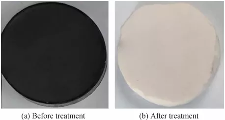
The XRD patterns and microstructure of Cf and Cf/SiC are shown in Fig. 2. The amorphous diffraction peak of C was detected near 2θ = 25.5° in untreated Cf samples. In addition to the amorphous diffraction peaks of C, the diffraction peaks of SiC at 35.6°, 60.1°, and 71.9° were also found in the XRD patterns of Cf/SiC samples [23,25,26], which further indicated the existence of SiC coating. It can be seen from Figs. 2(b)–2(d) that the carbon fiber bundles are evenly arranged. The diameter of carbon fiber monofilament is about 6–7 μm. SiC coating uniformly covers carbon fiber, and the thickness of the SiC coating is about 300 nm.

Fig. 2 (a) XRD patterns of Cf preform and SiC coating coated Cf preform and (b–d) SEM images of Cf preform and SiC coating coated Cf preform at different magnification.
Archimedes drainage method was used to test the bulk density and porosity of Cf/SiC/SiHfBOC composites under different PIP cycle times. The specific results are shown in Table 1. With the increase of PIP cycle times, the density of Cf/SiC/SiHfBOC composites increases gradually while the porosity decreases gradually. The density of untreated Cf preform is 0.35 g/cm³, and its porosity is 85.73%. The density of Cf/SiC preform is 0.50 g/cm³, and its porosity is 74.86%. After the third PIP cycle time, the density of Cf/SiC/SiHfBOC composites was 1.02 g/cm³, and its porosity was 47.98%. The density of Cf/SiC/SiHfBOC composites increased by about 0.12 g/cm³ after the third to fifth PIP cycle time, and its density growth rate gradually slowed down. After the seventh PIP cycle time, the density of Cf/SiC/SiHfBOC composites increased only by 0.03 g/cm³, so the density of Cf/SiC/SiHfBOC composites has reached the upper limit.
Table 1 Density and porosity of Cf preform, Cf/SiC preform, and Cf/SiC/SiHfBOC composites

Figure 3 is the SEM images of Cf/SiC/SiHfBOC composites after different PIP cycle times. According to Table 1, the density of the composites increases with the increase of PIP cycle times. In Fig. 3(a), the Cf/SiC/SiHfBOC-4 was prepared after four PIP cycle times, with a density of 1.15 g/cm³ and a porosity of 41.35%. Therefore, a great number of pores can be observed in the fiber preform body, and many carbon fibers have not been filled by SiHfBOC ceramics. The Cf/SiC/SiHfBOC-5 was prepared after five PIP cycle times, with a density of 1.27 g/cm³ and a porosity of 36.84% (Fig. 3(b)). However, there are still many holes in the composites, and it is observed that the carbon fiber not coated by SiHfBOC ceramics has decreased significantly. The Cf/SiC/SiHfBOC-6 was prepared after six PIP cycle times. Its density is increased to 1.37 g/cm³, and the porosity is 33.44% (Fig. 3(c)). It is observed that the pores in the composites have been further reduced, and most of the carbon fibers are covered by SiHfBOC ceramic, and the internal filling is relatively complete. The Cf/SiC/SiHfBOC-7 was prepared after seven PIP cycle times as in Fig. 3(d), and the surface of the carbon fiber in the composites is almost completely wrapped by SiHfBOC ceramic. Now its density is increased to 1.40 g/cm³, and the porosity is 28.87%. SiHfBOC ceramic covered most of the carbon fibers, which was the composites filled with SiHfBOC ceramic matrix. There are only a few holes in the composite, and the maximum pore width is about 3 μm. With the increase of PIP cycle times, the spacing of fibers is uniform, and the surface pores are gradually reduced.

Fig. 3 SEM images of Cf/SiC/SiHfBOC composites after different PIP cycle times: (a) 4 PIP cycle times, (b) 5 PIP cycle times, (c) 6 PIP cycle times, and (d) 7 PIP cycle times.
It is found that the microstructure and density of the composites can be controlled by the different PIP cycle times, and the macro and micropores in the composites are greatly reduced after seven times of impregnation and pyrolysis.
3. 2 Study and analysis of oxidation resistance of Cf/SiC/SiHfBOC composites
The oxidation behavior of Cf/SiC/SiHfBOC composites at different PIP cycle times is evaluated by XRD and SEM. The XRD phase diagram of Cf/SiC/SiHfBOC-7 composites oxidized at 1100℃ for 10 min is shown in Fig. 4. It indicates that not only the diffraction peaks of SiC and HfO2 are detected [27], but also the diffraction peaks of HfSiO4 are detected at 20.0°, 27.1°, 44.0°, and 53.7° after oxidation tests [28].

Fig. 4 XRD patterns of Cf/SiC/SiHfBOC-7 composites before and after oxidation.
The SiHfBOC ceramic content in the sample was less (Figs. 5(a) and 5(b)), and foamy oxidation products were formed after oxidation at 1100℃ for 10 min. In Fig. 5(c), filamentous oxidation products and obvious pores were observed. The surface porosity of the sample decreased significantly, when the PIP cycle times reached 7 (Fig. 5 (d)). From the local enlarged Fig. 5(e), the surface of carbon fiber in the composites is completely wrapped by SiHfBOC ceramic, and the SiHfBOC ceramic on the surface of carbon fiber is oxidized by O2 to form particles with different volumes. In Fig. 5, the Cf/SiC/SiHfBOC composites were gradually filled and the surface was gradually dense after oxidation, as the increase of PIP cycle times. There were filamentous oxidation products, and the pores were also more obvious (Fig. 5(c)). The pores on the surface of Cf/SiC/SiHfBOC-7 were significantly reduced after oxidation. From Fig. 5(e), the SiHfBOC ceramic on the surface of the carbon fiber is oxidized to form particles with different volumes. Figure 5(e) shows the weight retention ratio of Cf/SiC/SiHfBOC composites with different PIP cycle times after oxidation. The weight retention ratio of the composites increases from 93.43% to 98.75%, when the PIP cycle times increase from 4 to 7. Then analyzed with Fig. 5 and Table 1, it can be found that the pore of the Cf/SiC/SiHfBOC composite surfaces gradually decreases with the increase of PIP cycle times. At the same time, the contact area between carbon fiber and oxygen is gradually decreasing, so the oxidation resistance of the composites is also improved.

Fig. 5 SEM images and weight retention ratio of Cf/SiC/SiHfBOC composites with different densities oxidized at 1100℃ for 10 min: (a) 4 PIP cycle times, (b) 5 PIP cycle times, (c) 6 PIP cycle times, and (d, e) 7 PIP cycle times, and (f) weight retention ratio.
Figure 6 exhibits the SEM images and EDS surface scanning analysis of the Cf/SiC/SiHfBOC-7 after oxidation at 1100℃ for 10 min. In Figs. 6(a) and 6(g), there are many spherical particles attached to the top of the carbon fiber in Cf/SiC/SiHfBOC composites, which are similar in volume and evenly distributed. The EDS surface scanning results of the oxidized composites are shown in Figs. 6(b)–6(f), from which the distribution position and uniformity of Si, Hf, B, O, and C on the z-direction surface of the oxidized Cf/SiC/SiHfBOC composites can be seen. According to the atomic content ratio in Fig. 6(h), the Si, Hf, O, and C are the most abundant elements, while the B element is relatively low. This is mainly due to the B element escaping in the form of B2O3 during the oxidation process.

Fig. 6 SEM images and EDS diagram of Cf/SiC/SiHfBOC composites after oxidation at 1100 for 10 min.
The Cf/SiC/SiHfBOC-7 samples were subjected to a static oxidation treatment in a muffle furnace at 1200, 1300, 1400, and 1500℃ for 10 min. The micromorphology of samples after static oxidation treatment at different temperatures is shown in Fig. 7. There are bare Cf/SiC and large pores on the surface of the samples after oxidation at 1200℃ (Figs. 7(a) and 7(e)), which further form oxygen channels to accelerate the internal oxidation of the composite. The surface of the sample with the same density is gradually filled and coated by the molten oxide layer (Figs. 7(b)–7(d) and 7(f)–7(h)) with the increase of oxidation temperature, and thus its pores gradually decrease. After oxidation at 1500℃ for 10 min, a dense oxide film has been formed on the surface of the sample. SiC oxidizes slowly at 1300 ℃ and forms a SiO2 film on the surface, which hinders oxygen erosion [29]. However, the oxidation resistance temperature limit of Cf/SiC composites is about 1650℃ , and the transition of SiC matrix from passive oxidation to active oxidation is less than 1700℃ [30]. In our previous results, SiHfBOC ceramics have a good oxidation resistance at 1400℃ [3].

Fig. 7 SEM images of Cf/SiC/SiHfBOC composites after 10 min of oxidation at different oxidation temperatures: (a, e) 1200℃ , (b, f) 1300℃, (c, g) 1400℃, and (d, h) 1500℃.
Figure 8 shows the XRD patterns and weight retention ratio of the Cf/SiC/SiHfBOC composites after oxidation at 1200, 1300, 1400, and 1500℃ for 10 min. The oxidized sample is mainly composed of SiC, m-HfO2, and HfSiO4, where the diffraction peaks of SiC and part of the diffraction peaks of HfSiO4 overlap (Fig. 8(a)). When the oxidation temperature is 1200℃ , the m-HfO2 in the sample is the main crystalline phase. As the oxidation temperature increases, it is found that the diffraction peak of m-HfO2 gradually decreases, and the diffraction peak of HfSiO4 gradually increases. This indicates that m-HfO2 and SiO2 in Cf/SiC/SiHfBOC composites are more likely to react to form HfSiO4 in an oxidizing environment with higher temperatures. The weight retention ratio of the composites decreases from 96.05% to 94.85% (Fig. 8(b)) when the oxidation temperature increases from 1200 to 1500℃ . With the increase of oxidation temperature, the weight retention ratio of Cf/SiC/SiHfBOC composites gradually decreases, but the decreasing range is small. It shows that as the oxidation temperature increases, the surface dense oxide film of the sample’s reaction with oxygen becomes severe gradually. Thus the oxidation resistance of the Cf/SiC/SiHfBOC composites at high temperature also decreases. Borosilicate and SiO2 glass phase are formed on the surface at 1200℃ , and SiO2 glass phase is formed at 1400℃. When the oxidation temperature exceeds 1200℃ , the B2O3 in the composites begins to volatilize, thus gradually losing their oxidant resistance effect. Therefore, for Cf/SiC/SiHfBOC composites, the SiO2 film and HfSiO4 formed in the oxidation process is the main oxidant resistance effect in a short time at 1200–1500℃.

Fig. 8 (a) XRD patterns and (b) weight retention ratio of Cf/SiC/SiHfBOC composites after 10 min oxidation at different oxidation temperatures.
The micromorphology of the Cf/SiC/SiHfBOC-7 composites after a static oxidation treatment at 1500℃ in a muffle furnace for 30, 60, 90, and 120 min is shown in Fig. 9. As the oxidation time increases, the surface of the composites becomes denser and the pores are gradually filled. In Figs. 9(a) and 9(e), the sample oxidized at 1500℃ for 30 min has no obvious pores, but the surface is rough. In Figs. 9(b) and 9(f), the sample oxidized at 1500℃ for 60 min has some small pores, but the surface roughness decreases. In Figs. 9(c) and 9(g), the pores on the surface of the sample after oxidation at 1500℃ for 90 min are the largest, and the distribution is uneven, but the surface is relatively flat. The results show that a large amount of CO2, CO, B2O3, and other gases escape during the oxidation process of Cf/SiC/SiHfBOC-7 composites, and therefore many pores are formed on the surface of the samples. In Figs. 9(d) and 9(h), the pores on the surface of the sample oxidized at 1500℃ for 120 min are smaller and the surface is the flattest. At the same time, molten SiO2 and borosilicate glass phases are produced under high-temperature oxidation conditions to fill the surface, thereby gradually being smooth and dense. It indicates that the volatile gas in the oxidation process was evaporated. However, after oxidation at 1500℃, the surface oxide film in the early stage is not dense and some holes are formed, which leads to the formation of oxygen channels, resulting in the overall decrease of the weight retention rate of the Cf/SiC/SiHfBOC-7 composites. However, the slight increase of weight retention rate in the later stage also indicates that part of oxygen is absorbed and retained in the Cf/SiC/SiHfBOC-7 composites during the oxidation reaction process, which makes the surface of the Cf/SiC/SiHfBOC-7 composites gradually dense.

Fig. 9 SEM images of Cf/SiC/SiHfBOC composites after different oxidation time at 1500℃ : (a, e) 30 min, (b, f) 60 min, (c, g) 90 min, and (d, h) 120 min.
Figure 10(a) exhibits the XRD patterns of the Cf/SiC/SiHfBOC-7 composites after oxidation at 1500℃ for 30, 60, 90, and 120 min. The diffraction peaks of crystalline SiO2 were observed at 22.0° in the XRD curves of samples oxidized for 60, 90, and 120 min. Meanwhile, with the increase of oxidation time, the diffraction peaks of crystalline SiO2 and m-HfO2 gradually decrease, while the diffraction peaks of HfSiO4 gradually increase. It shows that the chemical reaction of crystalline SiO2 and m-HfO2 is easier to produce HfSiO4 under the condition of long-time high-temperature oxidation. The oxidation products of Cf/SiC/SiHfBOC-7 composites are mainly composed of HfSiO4, m-HfO2, SiO2, and SiC. In Fig. 10(b), the weight retention of Cf/SiC/SiHfBOC-7 composites increases firstly, then decreases, and then increases with an extension of oxidation time, but it generally shows a decreasing trend. On the whole, the weight reduction of Cf/SiC/SiHfBOC-7 composites is very small. According to the analyses in Fig. 9, the Cf/SiC/SiHfBOC-7 composites are seriously oxidized with the prolongation of oxidation time, and high-temperature oxidation resistance is gradually weakened. It also indicates that Cf/SiC/SiHfBOC-7 composites still have a high weight retention ratio after oxidation at 1500℃ for 120 min. However, the weight retention ratio of Cf/SiC/SiHfBOC-7 composites after oxidation at 1500℃ for 120 min is roughly the same as that after oxidation for 90 min, indicating that the weight change of the composites after oxidation for 90 min reaches a dynamic equilibrium.

Fig. 10 (a) XRD patterns and (b) weight retention ratio of Cf/SiC/SiHfBOC composites after oxidation at 1500℃ with different oxidation time.
The main phases of the Cf/SiC/SiHfBOC composites prepared in this article mainly include Cf, SiC, HfO2, BCxO3−x, B(SiO)3, and SiOxCy according to the above data and Refs. [2,14,15,28]. Therefore, the high-temperature oxidation mechanism of Cf/SiC/SiHfBOC composites is analyzed, and the possible chemical reaction formulas under high-temperature oxidation conditions are as follows [24,29–34]:
Cf + O2 → CO(g) (450 ℃) (6)
Cf + O2 → CO2(g) (450 ℃) (7)
B2O3(l) → B2O3(g) (1000 ℃) (8)
HfO2(s) + SiO2(s) → HfSiO4(s) (1100 ℃) (9)
BCxO3−x(s) + O2(g) → B2O3(g) + CO2(g) (1200 ℃) (10)
B(SiO)3(s) + O2(g) → B2O3(g) + SiO2(s) (1200 ℃) (11)
SiOxCy(s) + O2(g) → SiO2(s) + SiC(s) (1300 ℃) (12)
SiC(s) + O2 → SiO2(s) + CO2(g) (1300 ℃) (13)
SiC(s) + O2 → SiO2(s) + CO(g) (1300 ℃) (14)
Comparing the Gibbs free energy of each phase composition in Cf/SiC/SiHfBOC composites, it is found that the Gibbs free energy of the reaction between SiC and O2 is the lowest [35,36]. According to the morphology, XRD phase diagram, and the above chemical reaction formula under different oxidation conditions, the oxidation behavior can be divided into three parts:
(1) The oxidation temperature rises from room temperature to 1100 ℃. Due to the difference in thermal expansion coefficients of each phase’s composition and the volatilization of gaseous components, it can be seen from the SEM that there are many cracks and pores on the surface of the composites. B2O3 glass phase is formed on the surface of the sample below 1000 ℃. Although the generated B2O3 has certain fluidity in this temperature range, it can protect the composites to a certain extent. However, due to the low B element content in the material, the defects of the surface of the composites cannot be healed. When the temperature continues to rise, the generated B2O3 gradually begins to volatilize. The process continues from a low temperature to a high temperature, while a small amount of HfSiO4 is generated.
(2) The oxidation temperature rises from 1200 to 1500 ℃. Borosilicate and SiO2 glass phases are formed on the surface at 1200 ℃, and SiO2 glass phase is formed at 1400 ℃, and thus the fluidity of the surface of the composites is greatly improved. The cracks on the surface of the composites are gradually healed, leaving only a few holes. At this time, the oxygen channel is gradually blocked, so that oxygen atoms can no longer enter the interior of the composites to react. Therefore, the thickness of the oxide layer decreases, and the generation of HfSiO4 gradually increases with increasing temperature.
(3) After oxidation at 1500 ℃ for 30 min, there are many pores on the surface of the composites. The crystalline SiO2 appeared after oxidation at 1500 ℃ for 60 min of the composites. With the extension of the oxidation time, the peak of crystalline SiO2 decreases gradually with the oxidation time and it is highly likely that the reaction of SiO2 with HfO2 forms hafnium silicate. However, with the extension of the oxidation time, the peak intensity of crystalline SiO2 gradually was weakened, while the content of HfSiO4 gradually increased.
3. 3 Characterization of mechanical properties and analysis of strengthening–toughening of Cf/SiC/SiHfBOC composites
Figure 11 shows the compressive strength of Cf/SiC/SiHfBOC composites in x/y- and z-directions under different PIP cycle times. The mechanical properties of the Cf/SiC/SiHfBOC composites were improved with the increase of PIP cycle times. The compressive strength of samples after three PIP cycle times in the x/y- and z-directions is 31.32±6.12 and 9.31±1.23 MPa, respectively. After five PIP cycle times, the compressive strength of Cf/SiC/SiHfBOC-5 was 71.97±8.97 MPa in the x/y-direction, and 23.92±4.11 MPa in the z-direction. The density of Cf/SiC/SiHfBOC-7 was the highest after seven PIP cycle times, and the compressive strength of Cf/SiC/SiHfBOC-7 increased slightly in the x/y- and z-directions to 77.56±8.56 and 40.03±5.48 MPa, respectively. The increase of compressive strength decreases with the increase of PIP cycle times. As shown in Fig. 11, the compressive strength of Cf/SiC/SiHfBOC composites in x/y- and z-directions is positively correlated with PIP cycle times of the sample. Besides, the compressive property of the samples with the same PIP cycle times in the x/y-direction is higher than that in the z-direction. The main reason is that the fiber arrangement mode of the three-dimensional carbon fiber preform is that the two-dimensional carbon fiber cloth is arranged along the z-direction, and the z-direction is the needling process.

Fig. 11 Compressive strength of Cf/SiC/SiHfBOC composites with different PIP cycle times.
In Fig. 12, the compressive strength–strain curves of Cf/SiC/SiHfBOC composites consist of three stages:
(1) In the elastic strain stage, the whole structure of the sample is not damaged until the compressive strength reaches the maximum value, and the stress–strain curve appears an inflection point. Then the internal structure of Cf/SiC/SiHfBOC composites starts destructed. The initial corresponding slope is the elastic modulus of the composites, that is the compressive modulus.
(2) The yield stage of Cf/SiC/SiHfBOC composites is also called the strain strengthening stage, on which an irreversible inelastic deformation occurs.
(3) In the destruction stage, the composites are seriously damaged and the structure collapses.

Fig. 12 Compressive strength–strain curves of Cf/SiC/SiHfBOC composites with different PIP cycle times: (a) x/y-direction and (b) z-direction.
The compressive strength–strain curve in the x/y-direction is obvious changed (Fig. 12(a)) with the increase of PIP cycle times of Cf/SiC/SiHfBOC composites. It can be seen from the first elastic strain stage that the compressive strength reaches the maximum value when the PIP cycle times is 6, and the composite itself has a large deformation. There are only two stages in the compressive strength–strain curve of Cf/SiC/SiHfBOC composites in the z-direction (Fig. 12(b)), namely, an elastic stage and a yield stage. The reason is that only part of the fiber bundle breaks in the z-direction of the sample under the external load, while the fiber cloth layers perpendicular to the z-direction start to stack without being damaged, and thus the stress–strain curve of the composite rises continuously.
As shown in Fig. 13(a), the x/y- and z-flexural strengths of Cf/SiC/SiHfBOC-3 composites are 43.12±4.18 and 4.93±0.85 MPa, respectively. The flexural strength of Cf/SiC/SiHfBOC-5 composites reaches 51.27±4.55 MPa in the x/y-direction and 6.84±1.44 MPa in the z-direction after five PIP cycle times. The flexural strength of Cf/SiC/SiHfBOC in the x/y- and z-directions is 59.94±4.24 and 12.47±2.17 MPa, respectively, after seven PIP cycle times. Figure 13(b) shows the flexural strength–displacement curves of Cf/SiC/SiHfBOC composites after oxidation at five different PIP cycle times. The three stages of flexural strength–displacement curves in the x/y-direction of Cf/SiC/SiHfBOC composites are obvious with the increase of oxidation temperature. It can be seen from the first elastic stage that the flexural strength of composites reaches the maximum value when the PIP cycle times are the maximum, and the composites themselves have a large deformation.

Fig. 13 (a) Flexural strength and (b) flexural strength–displacement curves of Cf/SiC/SiHfBOC composites with different PIP cycle times in the x/y- and z-directions.
In Table 2, the fracture toughness values of Cf/SiC/ SiHfBOC-3, Cf/SiC/SiHfBOC-5, and Cf/SiC/SiHfBOC-7 are 1.71±0.29, 4.33±0.31, and 5.16±0.59 MPa·m1/2, respectively. With the increase of PIP cycle times, the fracture toughness also increases. However, because the whole Cf/SiC/SiHfBOC composites have a certain porosity, the fracture toughness of the composite is also not very high.
Table 2 Fracture toughness of Cf/SiC/SiHfBOC composites

The fracture morphology of Cf/SiC/SiHfBOC composites is shown in Fig. 14. In this work, to overcome the intrinsic brittleness of ceramics, the continuous carbon fiber was selected as the second phase to toughen. The continuous carbon fibers added to the SiHfBOC ceramic matrix are arranged orderly in the SiHfBOC ceramic matrix, which can greatly improve the flexural strength of Cf/SiC/SiHfBOC composites. During the process of an elastic deformation stage, the continuous carbon fiber absorbs a large amount of energy, and much of its mechanical energy absorbed is transferred to the surface of carbon fiber, which is mismatched with the ceramic matrix and further beginning deboned [37]. In Fig. 14(b), as the load continues to increase, the crack interface between continuous carbon fiber and ceramic matrix begins to loosen, resulting in stress relaxation. The ceramic matrix is damaged and then spalling occurs. The continuous carbon fiber is exposed, which is called the fiber pull-out phenomenon. When the carbon fiber is pulled out, it will continuously absorb the external energy as much as possible. Figure 14(c) indicates that a continuous carbon fiber begins to fracture. In the three-point bending test, the carbon fiber would absorb energy and occur on deformation when the crack propagates to the surface of the carbon fiber through the ceramic matrix. Exceeding the bearing capacity limit of carbon fiber, it cannot absorb energy and finally get fractured. After the fracture, the carbon fiber will recover into the original state, and then release the energy absorbed before. It shows that the strengthening–toughening mechanism of Cf/SiC/SiHfBOC composites is mainly composed of fiber debonding, fiber pulling out, and fiber fracturing. The debonding and pull-out of continuous carbon fibers play an important role in the failure of Cf/SiC/SiHfBOC ceramic matrix composites during the flexural fracture experiments.

Fig. 14 Fracture morphology of Cf/SiC/SiHfBOC composites: (a) fiber debonding, (b) fiber pulling out, and (c) fiber fracture.
The compressive strength of Cf/SiC/SiHfBOC composites in x/y-direction has three stages, which are representative of this research. Therefore, an analysis of oxidative compressive strength in x/y-direction is taken as the object of research. The compressive strength and compressive strength–strain curves of Cf/SiC/SiHfBOC-7 composites after oxidation at five oxidation temperatures are shown in Fig. 15. The compressive strength in the x/y-direction of Cf/SiC/SiHfBOC-7 composites after oxidation at 1100, 1200, 1300, 1400, and 1500℃ for 10 min is 75.16±8.17, 64.93±7.22, 60.53±7.01, 55.19±5.25, and 39.59±4.78 MPa (Fig. 15(a)), respectively. The results show that the compressive strength of Cf/SiC/SiHfBOC composites decreases with the increase of oxidation temperature. The compressive strength decreased to 96.90% after oxidation at 1100℃ and 51.03% after oxidation at 1500℃ , but it still kept the mechanical properties after a short time of high-temperature oxidation. Three stages of the stress–strain curve in the x/y-direction can be observed (Fig. 15(b)). At the first elastic stage of all composites, the compressive strength is the largest and the deformation is the smallest when the oxidation temperature is 1100℃ . According to the analyses of Figs. 7, 8, and 11, it is found that when the surface of Cf/SiC/SiHfBOC composites was oxidized at 1100℃ for 10 min, oxygen in the air failed to enter the interior of Cf/SiC/SiHfBOC composites to corrode it. However, as the oxidation temperature was risen into 1500℃ , its surface layer was not completely healed, and oxygen channels were formed to conduct a large amount of oxidation in the interior of the composite, resulting in a substantial attenuation of the compressive strength of Cf/SiC/SiHfBOC composites.

Fig. 15 (a) Compressive strength and (b) compressive strength–strain curves of Cf/SiC/SiHfBOC composites in the x/y-direction at different oxidation temperatures.
Figure 16 exhibits the compressive strength and compressive strength–strain curves of Cf/SiC/SiHfBOC-7 composites after oxidation at 1500℃ . The compressive strength of Cf/SiC/SiHfBOC-7 composites in the x/y-direction is 30.38±3.55, 23.88±3.11, 18.68±2.34, and 16.50±2.08 MPa after oxidation at 1500℃ for 30, 60, 90, and 120 min, respectively. The compressive strength decreased to 39.17% after 30 min oxidation, 24.08% after 90 min oxidation, and 21.27% after 120 min oxidation. The results show that the compressive strength of Cf/SiC/SiHfBOC-7 composites decreases with the increase of oxidation time, and the compressive strength changes little after oxidation at 1500℃ for 90 and 120 min. Figure 16(b) shows the stress–strain curves of Cf/SiC/SiHfBOC-7 composites after oxidation at 1500℃ for different time. Three stages of the stress–strain curve in the x/y-direction can be presented in Fig. 16(b) accompanied by an increase of oxidation time. From the first elastic stage, when the oxidation time is 30 min, the compressive strength reaches the maximum value, and the sample itself has a large deformation. Moreover, the strain range of the yield point at the first stage is between 2% and 7%. After reaching the yield point, stress yield begins to occur. Based on the analyses of Figs. 9 and 10, it is found that when the Cf/SiC/SiHfBOC composites were oxidized at 1500℃ for 30 min, oxygen in the air would form the oxygen channels and then conduct a large amount of oxidation in Cf/SiC/SiHfBOC composites. However, after oxidation at 1500℃ for 120 min, the attenuation range of compressive strength property was obviously weakened, indicating that oxide layer on the surface of Cf/SiC/SiHfBOC composites gradually was healed and played a certain barrier role. Meanwhile, it still had a good compressive performance after oxidation at 1500℃ for 120 min, which indirectly proved its excellent oxidation resistance.

Fig. 16 (a) Compressive strength and (b) compressive strength–strain curves of Cf/SiC/SiHfBOC composites in the x/y-direction at different oxidation time.
4 Conclusions
In this article, the on-demand preparation of Cf/SiC/SiHfBOC composites is realized, to control the microstructure and properties of the composites. When the PIP cycle times were increased from 3 to 7, the density of the composites was added from 1.02 to 1.40 g/cm³, and the porosity decreased from 52.53% to 28.87%. And the compressive strength in the x/y- and z-directions was increased from 31.32±6.12 and 9.31±1.23 MPa to 77.56±8.56 and 40.03±5.48 MPa, respectively. The strengthening–toughening methods mainly include the fiber debonding, the fiber pulling out, and the fiber breaking. The products of Cf/SiC/SiHfBOC composites after the static oxidation tests mainly include CO2, CO, B2O3, SiO2, HfSiO4, etc. In terms of the analyses on compressive stress–strain curve, oxidation weight retention rate, and oxidation surface SEM, it was found that the weight retention and compressive strength of Cf/SiC/SiHfBOC-7 sample were 83.97% and 23.88±3.11 MPa, respectively, after being oxidized at 1500 ℃ for 60 min, which further proved that the Cf/SiC/SiHfBOC composites could be used in an oxidation environment at 1500 ℃ for a short time.
Reference: Omitted
Declaration: This article is provided by CERADIR™ users or obtained from Internet, the content does not represent the position of CERADIR™. We are not responsible for the authenticity/accuracy of the article, especially the effects of the products concerned. This article is for study only, it does not constitute any investment or application advice. For reprinting, please contact the original author. If it involves the copyright and/or other issues, please contact us and we will deal with it asap! CERADIR™ has the interpretation of this declaration.