Abstract: Melt-grown alumina-based composites are receiving increasing attention due to their potential for aerospace applications; however, the rapid preparation of high-performance components remains a challenge. Herein, a novel route for 3D printing dense (< 99.4%) high-performance melt-grown alumina-mullite/glass composites using directed laser deposition (DLD) is proposed. Key issues on the composites, including phase composition, microstructure formation/evolution, densification, and mechanical properties, are systematically investigated. The toughening and strengthening mechanisms are analyzed using classical fracture mechanics, Griffith strength theory, and solid/glass interface infiltration theory. It is demonstrated that the composites are composed of corundum, mullite, and glass, or corundum and glass. With the increase of alumina content in the initial powder, corundum grains gradually evolve from near-equiaxed dendrite to columnar dendrite and cellular structures due to the weakening of constitutional undercooling and small nucleation undercooling. The microhardness and fracture toughness are the highest at 92.5 mol% alumina, with 18.39±0.38 GPa and 3.07±0.13 MPa·m1/2, respectively. The maximum strength is 310.1±36.5 MPa at 95 mol% alumina. Strength enhancement is attributed to the improved densification due to the trace silica doping and the relief of residual stresses. The method unravels the potential of preparing dense high-performance melt-grown alumina-based composites by the DLD technology.
Keywords: laser; additive manufacturing; alumina; mullite; microstructure; mechanical properties
1 Introduction
Further development of hot-end components for advanced aero-engines and high-efficiency gas turbines and thermal protection systems for aircraft (e.g., re-entry space vehicles, rocket, and strategic bombers) is placing higher demands on structural materials. These requirements include higher temperature resistance, long-term mechanical properties, low density, oxidation resistance, and outstanding thermal shock resistance [1–4]. Due to the ability to maintain stable microstructure and excellent high-temperature mechanical properties over long periods at high temperatures, melt-grown alumina-based composites are significant candidates for such applications as combustion chamber liners, nozzles, heat shields, and possible blades. Typical material systems are eutectic, such as Al2O3/YAG (Y3Al5O12) [5], Al2O3/GAP (GdAlO3) [6], Al2O3/Er3Al5O12/ZrO2 [7]. In addition, low density is beneficial to reduce the weight of hot-end components and thermal protection systems, which significantly improves efficiency (e.g., chamber combustion efficiency) and reduces costs. The inherent oxidation resistance further ensures the stable operation of hot-end components and thermal protection systems under a high-temperature and high-pressure oxidation environment. These are the current limitations of traditional superalloys and SiC-based composites [8,9] in the above applications. As one of the melt-grown alumina-based composites, in addition to the excellent performance mentioned above, alumina–mullite composites (AMC) exhibit outstanding thermal shock resistance performance on account of appropriate porosity, suitable interfacial bonding, and low thermal expansion coefficient of mullite. For example, Zhang et al. [10] claimed that the AMC with a flexural strength of 494±25 MPa could be fabricated using the initial powder with nanometer size. Burgos-Montes et al. [11] pointed out that mullite could be used as a second phase to replace SiC to strengthen the alumina matrix. The strengthening mechanism was grain boundary strengthening at the alumina–mullite interface. Aksel [12] concluded that the resistance to crack initiation and propagation of the AMC caused by thermal stress was increased due to the shorter length needle-like mullite, enhancing residual strength and thermal shock resistance. It is worth noting that cheap raw materials and rich preparation methods are also reasons for the widespread application of the AMC [13,14]. Considering the outstanding performance and in-service/potential value, the AMC have received extensive attention. Therefore, the demand for lightweight, heat-resistant, and high-performance composites has promoted the development of melt-grown alumina-based composites, especially melt-grown AMC.
There are several preparation methods for the AMC, such as traditional sintering [15], microwave sintering [16], spark plasma sintering [17], direct laser sintering [18,19], layer-wise slurry deposition [20]. However, due to the complicated process or the presence of sintering aid, the high-temperature performance of composites is depressed, limiting their application in hot-end components and thermal protection systems [14]. In contrast, melt-grown alumina-based composites are expected to be applied in hot-end components and thermal protection systems by solving the above problems. The composite material usually refers to the alumina-based eutectic composites obtained from the melt by directional solidification (DS). These composites have excellent high-temperature strength and thermal stability, determined by fine microstructure and atomic bonding phase interface [21]. Based on this, in the past two decades, researchers had developed a variety of DS methods, such as Bridgeman [22], micropulling down (μ-PD) [23], laser floating zone (LFZ) [6], to prepare these composites. However, these methods have the disadvantages of a long preparation cycle, high energy consumption, and failure to form complex structures. Directed laser deposition (DLD) is a laser-assisted direct addition manufacturing technology, also known as laser engineered net shaping (LENS), which belongs to a kind of directed energy deposition (DED) technology [24,25]. This technology uses a high-energy laser beam to melt powder materials to form components on a substrate, enabling the rapid preparation of near net size complex three-dimensional components. It has the advantages of simple process, short cycle, and low cost, and has received continuous attention in the preparation of melt-grown oxide ceramic materials [26–29]. For instance, Balla et al.[30] used this method to prepare crack-free alumina ceramics. The alumina cellular structures arranged along the deposition direction determined the anisotropy of the sample (with compressive strength of 123 MPa along the deposition direction and 229 MPa perpendicular to the deposition direction). Niu et al. [31] used DLD technology to prepare Al2O3/ZrO2 melt-grown composites with a eutectic spacing of about 100 nm. The microhardness and fracture toughness were 17.15 GPa and 4.79 MPa·m1/2, respectively. Yan et al. [32] and Hu et al.[33] prepared melt-grown Al2O3/ZrO2 composites using DLD technology with ultrasonic assistance. They argued that under the conditions of ultrasonic assistance, the performance of composites could be improved through inhibiting pores/cracks and refining grains. Fan et al. [26] have successfully fabricated highly dense Al2O3/YAG/ZrO2 ternary eutectic melt-grown composites using this technology. Wu et al. [34], Li et al. [35], and Pappas et al. [36] investigated the effect of initial composition on Al2O3/ZrO2 melt-grown composits using this technology. They pointed out that adjusting the composition ratio of zirconia could suppress cracks and optimize the microstructure, improving the mechanical properties. However, to the best of our knowledge, preparing melt-grown AMC by the DLD technology has not been reported. The rapid preparation of melt-grown AMC can help fill the demand for high-performance composites of hot-end components and thermal protection systems.
This study aimed to prepare high-performance melt-grown ceramics melt-grown alumina–mullite/glass composites with different composition ratios using the DLD technology. The phase composition, microstructure formation/evolution, and mechanical properties of the composites were investigated and discussed. The effect of the initial compositions on the mechanical properties of the samples was investigated, and the mechanism of sample strengthening and toughening was analyzed in detail. This study provides a novel and detailed insight into high-performance melt-grown alumina–mullite/glass composites prepared by DLD technology. The results provide theoretical and technical guidance for the rapid preparation of ceramic matrix composites for hot-end components and thermal protection systems.
2 Experiment and method
2. 1 Initial powder
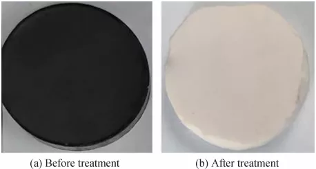
The powder used in this study was 99.5 wt% alumina (Bestry Performance Materials Co., Ltd., China) and ≥ 99.8 wt% silica (Al2O3 ≤ 1500 ppm, Fe2O3 ≤ 50 ppm; Beijing Sangyao Technology Development Co., Ltd., China) spherical powder. Figures 1(a) and 1(b) show the morphology of alumina and silica powder provided by the supplier, respectively, confirmed by XRD in the upper right corner. The silica powder was partial crystallization. The silica powder was treated with a coupling agent to improve the fluidity (Fig. 1(c)), which solved poor powder feeding or plugging of mixed powder containing silica. It can be found that there is no significant change in the morphology of the silica powder before and after the modification. The surface modification process has been described in the previous report [37]. First, a 5 wt% aqueous solution of aminosilane coupling agents (Qufu Chenguang Chemical Co., Ltd., China) was prepared and then stirred in an automatic mixer for 30 min to fully hydrolyze. Second, silica powder provided by the supplier was added in and stirred for 2 h at 200 rpm/min. The required silica powder was obtained by standing, drying, and sieving ultimately. The alumina powder provided by the supplier (Fig. 1(a)) and the modified silica powder (Fig. 1(c)) were all screened to ensure the diameter of 45–90 μm. Then, the powder was dried at 120 ℃ for more than 6 h to remove the moisture further. Five composition samples were designed with reference to the characteristics of the Al2O3–SiO2 phase diagram, referred to as AS70, AS80, AS90, AS92.5, and AS95, in which alumina accounted for 70, 80, 90, 92.5, and 95 mol%, respectively. Mechanical stirring for 1 h was performed to make the powder mix evenly. As shown in Figs. 1(d) and 1(e), with the increase of the alumina content in the initial powder, the Al element content gradually increased, and the Si element content gradually decreased.

Fig. 1 Powder for shaping. (a) Morphology of alumina powder, (b, c) morphology of silica powder before and after surface modification, respectively, (d) content of Al and Si elements with different composition ratios, and (e) EDS surface distributions of mixed powder.
2. 2 Shaping process
The experimental equipment for preparing melt-grown AMC by DLD mainly included JK1002 Nd:YAG continuous laser, CNC numerical control system, cooling system, and DPSF-D3 powder feeder [37]. The schematic diagram of the shaping samples is shown in Fig. 2. The dashed box was a schematic diagram of the shaping strategy realized by a program compiled by the CNC system. For each deposition layer shaped, the CNC workplace was lowered by a distance of the interlayer lift (∆z). The final cylindrical sample was composed of 85 layers. The cylindrical sample was selected to evaluate the flexural strength of composites. High purity argon (99.99%) was used to transport powder and protect the laser cladding head. Before deposition, a thin layer of graphite was coated on the alumina substrate (95% alumina, Xiyuan, XY-95, China) to increase laser absorption. The laser beam and powder stream waist were adjusted to converge on the substrate surface, H = 9 mm, to improve deposition efficiency. The process parameters (laser power, scanning speed, and interlayer lift) were sequentially set as constant. Correspondingly, the powder feeding rates of the AS70, AS80, AS90, AS92.5, and AS95 samples used in this study were 2.11, 2.22, 2.38, 2.47, and 2.51 g/min, respectively. The detailed shaping process parameters are shown in Table 1. During the shaping process, the mixed alumina and silica powder were delivered to the substrate surface using high-purity argon (99.99%). Under the irradiation of laser beam, the mixed powder melted rapidly, forming a tiny molten pool. When the laser beam left the active position, the irradiated part solidified immediately. This process was repeated continuously to form a cylindrical sample.

Fig. 2 Schematic diagram of DLD shaping samples.
Table 1 Process parameter of DLD cylindrical samples

2. 3 Characterization and detection
The transverse and longitudinal sections of the samples were ground with diamond discs (400#, 800#, 1500#, 2000#, and 3000#), and then polished with diamond polishing paste (2.5 μm). An X-ray diffractometer (XRD-6000, SHIMADZU, Japan) was used to analyze the phase composition. The operating voltage and current were 40 kV and 30 mA, respectively. The scanning speed was 4 (°)/min, and the scanning angle in the range of 2θ was 10°–80°. The crystal structure and phase interface were analyzed by transmission electron microscope (TEM; JEM-2100F, JEOL Ltd., Japan) and high-resolution transmission electron microscope (HRTEM; JEM-2100F, JEOL Ltd., Japan), and the working voltage was 200 kV. The TEM sheet was prepared by double beam focused ion beam/scanning electron microscope (FIB/SEM) on FEI Helios G4 UX (Thermo Fischer, USA). Before slicing, the sample surface was plated with carbon. A scanning electron microscope (SEM; Supra 55, Zeiss, Germany) was used to observe the polished sections’ microstructure. The grain size of corundum (α-alumina) in the samples was measured, referring to ASTM E112-13 [38]. The final grain size was the average of the three SEM photographs of each group samples.
The image processing method was used to obtain phase proportion from the SEM pictures. This method used the area ratio of phases to represent the volume ratio [39–41]. It was not easy to distinguish the two phases by adjusting the brightness and contrast in this study. Therefore, Photoshop software was used to cut out the corundum and fill it with white, as shown in Fig. 3. This method has certain subjective errors due to fine dendrites in samples prepared with low alumina content, which depended on the observer. The maximum error was not exceeding 1%. Then, the phase ratio was calculated by Image-Pro Plus 6.0. The white phase percentage was equal to the ratio of the white phase area to the total area of the picture. For the samples’ cross section and longitudinal section, at least three SEM images were counted.

Fig. 3 Schematic diagram of the phase proportion calculation of the melt-grown AMC.
The density and porosity were measured by Archimedes method and caliper [42,43]. The relative density of the samples was evaluated according to Eq. (1):
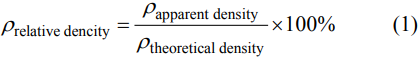
The theoretical density was calculated by the rule of mixtures (ROM):
Here, ρt is the theoretical density, ρti is the theoretical density of phase i (taken from the standard PDF card), Vi is the volume percentage of phase i , and i is the phase code. The apparent porosity (Pa) and real porosity (Pr) were

where ρb and ρa are the bulk density and apparent density (g/cm³), respectively. The bulk density was
Here, m1 is the dry weight of the samples (g), V is the volume of the samples (cm³), obtained by measuring the cuboid samples used for the three-point bending strength test by the vernier caliper, b is the width of the samples (mm), d1 is the thickness of the samples parallel to the loading direction (mm), and L1 is the span length (mm). The apparent density was

where Ve is the effective volume of the samples (cm³), ρ0 is the density of water (0.9986 g/cm³, water temperature was 18±0.2 ℃), and m2 is the floating weight (g). The indentation method was used to measure the microhardness of polished sections. The load was 4.903 N and the hold time was 15 s. The microhardness was calculated according to Eq. (7):

where HV is the Vickers hardness (GPa), FV is the test force (N), and d2 is the arithmetic average of the two diagonal lengths (mm). The microhardness was the average of ten indentation test results. The elastic modulus of the composites was calculated by the ROM [44,45]. The upper bound (assuming the same strain) and lower bound (assuming the same stress) of the elastic modulus were given by the Voigt model [46] (Eq. (8)) and the Reuss model [47] (Eq. (9)), respectively. The elastic modulus of the overall composites was the average of the upper and lower bounds. Among them, the elastic modulus of alumina was 380 GPa [48,49] and that of mullite was 223.3 GPa [50].

The fracture toughness of the samples were calculated according to the indentation morphology [51]:

where KIC is the fracture toughness (MPa·m1/2), EC is the elastic modulus of composites (GPa), which was given by the mixed criterion, such as Eqs. (8) and (9), Φ is the constraint factor, l is the crack length, that is, the distance from the diagonal end to the crack tip, and d2 is the diagonal dimension of the indentation. Since (l+d2 )/d2 was less than or equal to 2.5 for crack statistics, the crack length l here refered to the Palmqvist crack length. The cracks were radial cracks, namely Palmqvist cracks. Ultimately, the fracture toughness is the average of the ten indentation calculations. The flexural strength of the samples was evaluated according to the three-point bending mothed (ISO 14704: 2000). According to this standard, the shaped cylindrical samples were carefully ground with 400#, 800#, 1500#, and 2000# diamond discs to form cuboid samples for the three-point bending test, without further pressing them. In this case, the span distance was 30 mm and the beam movement speed was 0.5 mm/min. The flexural strength of the samples was

where σf is the flexural strength (MPa), F is the maximum load (N), and L2 is the span (mm). The flexural strength was the average of the calculated results for ten samples.
3 Results and discussion
3. 1 Microstructure
Figure 4 shows the microstructure of the melt-grown AMC prepared by DLD. With the increase of alumina content in the initial powder, the microstructure of the melt-grown AMC showed significant changes. First, when the alumina content was low (70 mol%, AS70), the content of the corundum phase precipitated from the melt was low (~24.2 vol%). The corundum grains exhibited short discrete dendrites (visually manifested as bumps, Fig. 4(a)), regularly arranged in continuous mullite phase (Fig. 4(b)), in near equiaxed dendrites. Some dendrite arms of each equiaxed dendrite have well-developed growth. With the alumina content increased up to 80 mol% (AS80), the corundum dendrites transformed into long columnar dendrite structures with directional alignment along the deposition direction (Fig. 4(c)). The SEM picture of the cross section reveals the growth of arranged corundum dendrites (Fig. 4(d)). The proportion of corundum phase at this ratio was ~31.7 vol%. As the alumina content increased to 90 mol% (AS90), the content of the corundum phase increased significantly (~75.1 vol%). The directionally aligned corundum dendrites grew further (Fig. 4(e)). The SEM photograph of the cross section shows incomplete corundum grains with mullite phases of small pore morphology distributed inside (Fig. 4(f)). In the AS92.5 samples, the content of the precipitated corundum phase increased, and the mullite phase further decreased. The corundum columnar dendrite structures gradually transformed into cellular structures (Figs. 4(g) and 4(h)). When it reached 95 mol% (AS95), the corundum grains formed cellular structures (Figs. 4(i) and 4(j)), where the length of cellular structures was about 83.7±12.8 μm, and the diameter was about 15.8±1.3 μm. The anisotropic growth was more obvious than that of AS92.5. The SEM picture of the cross section shows larger corundum grains with an approximately equiaxed morphology (Fig. 4(j)). The two-phase content in the melt-grown AMC is shown in Table 2. In this study, the composition of the initial powder for shaping melt-grown AMC was designed based on the Al2O3–SiO2 phase diagram, where the alumina content was designed to increase gradually. The AS70 samples were close to the stoichiometric mullite end (60 mol%), and AS80 samples were close to the high alumina end of high alumina–mullite (60 mol% Al2O3 to 75 mol% Al2O3). Therefore, for the AS70 and AS80 samples, mullite tends to form high alumina–mullite with higher alumina content [52]. As a result, the corundum precipitation of these two samples is low, and silica in the initial powder is mainly used to form high alumina–mullite. In addition, the results of numerical simulations pointed out a melt pool temperature of ~3000 ℃ for the preparation of melt-grown ceramics by the DLD [53]. The laser power used in this study is less than the previous study (350 W), so the temperature that the melt pool can reach will be less than 3000 ℃. According to the CRC Handbook of Chemistry and Physics [54], the boiling point of silica is 2950 ℃. Therefore, the evaporation of silica in the DLD preparation melt-grown AMC is possible. However, the amount of silica evaporation needs to be investigated further. Furthermore, AS90, AS92.5, and AS95 samples were prepared from initial powder over high alumina–mullite ratios. Therefore, the corundum phase in these samples will precipitate gradually according to the Al2O3–SiO2 phase diagram, which is determined by the composition of the initial powder. Consequently, the AS90, AS92.5, and AS95 samples have higher corundum phase content than AS70 and AS80.

Fig. 4 Microstructure of the melt-grown AMC prepared by DLD (obtained by SEM).
Table 2 Phase proportion of melt-grown alumina– mullite/glass composites prepared by DLD

Figure 5 shows a high-magnification SEM photograph (Fig. 5(a)) and EDS analysis patterns (Figs. 5(b)–5(d)) obtained on the longitudinal section of the AS90 sample. The visually depressed continuous phase was mullite, composed of silicon, aluminum, and oxygen elements, with silicon-rich elements and poor aluminum elements. The EDS point scan results indicated that the continuous phase was high alumina–mullite (Fig. 5(c)). The visually convex “fishbone” phase was the corundum phase, composed of oxygen and aluminum. A small amount of aluminosilicate glass phase was distributed between continuous mullite, rich in silicon, and poor in aluminum (Figs. 5(b), 5(d), and 5(e)).

Fig. 5 EDS analyses of the melt-grown AMC: (a) microstructure morphology, (b) surface distribution of all elements, (c) elemental content of point A and point B in (a), and distributions of (d) Al, (e) Si, and (f) O.
Figure 6 shows the XRD results of the melt-grown AMC. The AS70, AS80, AS90, and AS92.5 samples contained the alumina and mullite phases (red wireframe). The alumina phase was corundum (JCPDS Card No.46-1212), and the mullite phase was high alumina–mullite (PDF # 79-1450, Al4.95Si1.05O9.52). However, no peaks of mullite or broadened characteristic peak of the glass phase were detected in the AS95 sample, which was due to the low content of the other phase formed in the sample (~2.1 vol%). Further TEM studies showed that the AS95 sample consisted of two phases (Fig. 7(a)), confirmed by HRTEM images with inverse fast Fourier transform (IFFT) images and selected area electron diffraction (SAED) patterns as corundum (Figs. 7(b) and 7(c)) and glass phase (Figs. 7(e) and 7(f)). The lattice fringes of alumina showed crystal plane spacing of 0.238 nm, which was matched with (1¯1¯20) crystal planes of corundum (0.2379 nm). Furthermore, the glass thoroughly infiltrated on the alumina grain surface, which was similar to the alumina/glass reported by Hornberger et al. [55]. The alumina at the interface was a facet morphology (Fig. 7(d)).

Fig. 6 XRD analysis of the melt-grown AMC.

Fig. 7 TEM and HRTEM characterizations of the melt-grown AMC: (a, d) bright-field TEM images of phase interface, (b, c) SAED pattern and IFFT image of corundum for (1¯1¯20) planes on the zone axis [0001], respectively, (e) TEM image of glass phase and IFFT image in the inset, and (f) SAED pattern of glass phase.
A composition range of 70 to 95 mol% alumina in the initial powder was designed to investigate the effect of different alumina compositions on the melt-grown AMC, as shown in Fig. 8. The mechanism of crystallization from the melt is similar within this composition range. The AS90 sample is chosen to analyze the precipitation of each phase. During the sample forming process, the melt pool began to solidify after the laser left the irradiated position. When the melt pool temperature decreases below the liquid phase line (point G) of the composition, alumina begins to precipitate as the primary phase to form corundum crystals. Under the effect of forced dissipation of heat toward the substrate and the previous deposition layer, corundum crystals advance to the liquid phase in a directional arrangement along the deposition direction (Fig. 4(e)). After that, as the temperature decreases further, the corundum crystal content increases, and the melt composition will change from point G to point F in the direction shown by the arrow. The concentration of solute in the remaining liquid phase increases in the melt due to alumina precipitation. The solidification point of the melt gradually decreases and changes from point A to point B. When the temperature is lowered to 1890 ℃, mullite crystals precipitate near the corundum crystals, and their content gradually increases with a further reduction of the molten pool temperature until the remaining melt is consumed. A small amount of residual liquid phase forms a glassy phase under rapid solidification conditions (cooling rate can reach 104 K-1), distributed between the mullite crystals (Fig. 5). The glass phase was also found by de Paris et al. [56], Shieh et al. [57], Li et al. [58], Lawrence and Li [59], and Deng et al. [60] in their study of laser-induced alumina/silica system. The final microstructure of the melt-grown AMC is composed of corundum embedded in a continuously distributed mullite matrix, and there is a small amount of glass phase between mullite crystals. It is noteworthy that only corundum and glass phases were present in sample AS95, and no mullite phase was detected. This may be because the mullite liquid phase is easy to form glass [58] under conditions of low silica content in the initial powder and high cooling rate. The eutectic of silica and mullite shown at point E was not found in this study.
The difference in microstructure of the melt-grown AMC with different compositions can be explained by the classical nucleation theory and the constitutional supercooling theory. According to the classical nucleation theory, the following relationships exist for the heterogeneous nucleation at the front of the supercooling tip zone [62]:

where I is the heterogeneous nucleation rate, I0 is the per-exponential factor, a constant, ΔGn0f1(θ) is the nucleation work of heterogeneous nucleation, ΔGd is the diffusion activation energy, kB is the Boltzmann’s constant, θ is the contact angle, and T is the thermodynamic temperature. During the process of preparing the melt-grown AMC, the energy input into the molten pool can be regarded as a constant since the process parameters (P, v, and m· ) were determined. Some of this energy melted the powder to form a molten pool, and some raised the temperature of the molten pool. In this way, the lower the alumina content in the initial powder, the higher the temperature at which the molten pool rises. Therefore, the nucleation rate of the samples with low alumina content in the initial powder (e.g., AS70) is high, which is beneficial to the strengthening of the equiaxed zone [63]. Compared to the samples with high alumina content (e.g., AS92.5), samples with low alumina content (higher silica content) exhibit lower contact angles [64]. As a result, the nucleation subcooling is lower, which facilitates the strengthening of the equiaxed zone. Therefore, the samples with low alumina content tend to form equiaxed crystals. Moreover, according to the constitutional supercooling criterion proposed by Tiller et al. [65]:

where G is the temperature gradient, R is the solidification rate, m is the slope of liquidus line, C0 is the average of solute concentration in the melt, D is the diffusion coefficient, and k is the equilibrium segregation coefficient. The stability of the solid/liquid interface is affected by the external conditions (G and R ) and the material properties (C0 , D , m , k ). In general, with the decrease of R , m , C0 and the increase of G , D , k , the constitutional supercooling decreases. In this study, we believe that G/R should be a constant since the shaping process parameters are determined. Therefore, the crystal morphology evolution can be analyzed by the initial composition. For the alumina/silica material system, when the alumina content is low (sample AS70), the melt formed by the laser has a high silica concentration (C0) , promoting the constitutional supercooling of solid/liquid interface. In addition, the high content of silica increases the melt viscosity and decreases the D of solute in the melt, which also leads to a greater degree of constitutional supercooling. The large constitutional supercooling leads to a high number of corundum nuclei, which is beneficial for the formation of equiaxed crystals. According to the Al2O3–SiO2 phase diagram (Fig. 8), the precipitation content of corundum is low for this composition condition (AS70), and the remaining silica-containing liquid phase is high. The remaining silica-containing liquid phase provides sufficient conditions for the corundum nuclei to grow. When the content of equiaxed corundum crystals exceeds a certain percentage, an equiaxed growth of corundum crystals is formed. The unstable thermal gradient in the silica-containing liquid phase makes the corundum crystals finally show a near-equiaxed dendrite morphology (Fig. 4(a)). As the content of alumina in the initial powder increases (the content of doping silica decreases), C0 and D decrease, and the degree of constitutional undercooling at the solid/liquid interface decreases, forming the evolution pattern of near-equiaxed dendrite → columnar dendrite structures → cellular structures. For sample AS95, the complete infiltration of the glassy liquid phase on the corundum crystals led to a decrease in supercooling and an increase in nucleation temperature. The remaining silica-containing liquid phase is not nucleated to form a glass phase under rapid cooling conditions. Therefore, the mullite phase in sample AS95 was not detected by XRD and TEM. The grain size of the primary corundum phase increased with increasing alumina content in the initial powder (Table 3). According to the Al2O3–SiO2 phase diagram (Fig. 8), the corundum precipitation content increases with the increase of alumina content in the initial powder. Furthermore, each phase in the melt-grown ceramic prepared by DLD has the characteristics of single crystal growth [26]. Therefore, the grain size of the primary corundum phase is increasing when the corundum phase content increases.

Fig. 8 Modified phase diagram of alumina–silica. Reproduced with permission from Ref. [37], © Springer Science+Business Media, LLC, part of Springer Nature 2020.
Table 3 Density and grain size of the melt-grown AMC prepared by DLD

3. 2 Mechanical properties
3.2.1 Density and compactness
It can be observed from Table 3 that as the content of alumina in the initial powder increases, the density (theoretical density ρt , bulk density ρb , and apparent density ρa) gradually increases, and there is a relationship: ρt>ρa>ρb . Figure 9 shows the relative density and porosity of melt-grown AMC with different compositions. The relative density of sample AS70 was low at ~95%. The relative density increases with the increase of alumina content in the initial powder. The relative densities of samples AS90, AS92.5, and AS95 were about 98% or more. The highest relative density is 99.37%±0.07% when the alumina content is 95 mol% (AS95). The results of this study are higher than those of Zhang et al. [10] obtained by sintering alumina–5 vol% mullite composites (97.9%) and Viswabaskaran et al. [66] sintered AMC material (96%) by adding 3 wt% MgO. The porosity (apparent porosity and real porosity) of the composite material gradually decreased with the increase of the alumina content in the initial powder. When the alumina content in the initial powder was 95 mol% (sample AS95), the pores in the sample are mainly composed of closed pores distributed inside the sample (the porosity is 0.63%), and there are no apparent pores. Obviously, for samples with more alumina and less silica in the initial powder (AS90, AS92.5, and AS95), the addition of silica contributes to the improvement of the sample densification.

Fig. 9 Relative density and porosity of the melt-grown AMC prepared by DLD.
The theoretical density of corundum is 3.97 g/cm³ [34], and the theoretical density of mullite is 3.103 g/cm³.
3.2.2 Elastic modulus and microhardness
(1) Elastic modulus
Figure 10 shows the elastic modulus of the melt-grown AMC evaluated according to the Voigt model and the Reuss model. It can be seen that with the increase of the alumina content in the initial powder, the elastic modulus of the composite material gradually increases. The increase in elastic modulus can be attributed to the increase of corundum phase (Table 2) because the elastic modulus of corundum is about twice that of mullite.

Fig. 10 Voigt and Reuss model estimation results of elastic modulus.
(2) Microhardness
The microhardness of the melt-grown AMC as a function of alumina content is shown in Fig. 11. With the increase of alumina content, the microhardness first increased significantly and then decreased slightly. Specifically, the microhardness of the longitudinal section increased from 13.99±0.11 to 18.30±0.53 GPa, and then decreased to 18.12±0.46 GPa. The microhardness of the cross section increased from 14.54±0.23 GPa to the highest value (18.39±0.38 GPa) and then decreased to 17.55±0.31 GPa. These hardness values are higher than that of pure alumina prepared by traditional sintered 95 wt% alumina (5–12.4 GPa), and the AMC (Medvedovski [13] of 10.1–11.1 GPa, Zhang et al. [10] of 16.9±0.5 GPa, and Cascales et al. [67] of 13.5±0.1 GPa). However, it is still lower than the pure alumina ceramics prepared by the same method, which was ~18.91 GPa [68]. The overall microhardness of composites is higher than that of other methods, mainly due to the increase in relative density and the growth characteristics of single-crystal fibers. Also, the variation of microhardness can be explained by relative density, corundum phase content, and grain size. The increase of relative density is beneficial to increasing microhardness, attributed to the decrease of porosity and the improvement of densification due to the addition of silica. Besides, the increase of strengthening phase content is beneficial to increasing microhardness. With the increase of alumina content in the initial powder (AS70, AS80, AS90, and AS92.5), the precipitated corundum phase’s content gradually increases (Table 2 and Fig. 4). This changing trend of microhardness is consistent with the results predicted by the mixing criterion [36,45], as shown in Eqs. (9) and (10). Since the glass phase content in samples AS90, AS92.5, and AS95 is less than 3 vol%, the grain size of the composites can be evaluated by the grain size of corundum, as shown in Table 3. Compared with the sample AS92.5, the grain size of the sample AS95 is larger, so the microhardness of the composites decreases. The longitudinal section’s microhardness is generally smaller than that of the cross section. This may be because the grain size of corundum/mullite columnar dendrite structures or cellular structures in the longitudinal section is larger than that in the cross section.

Fig. 11 Vickers microhardness of the melt-grown AMC.
3.2.3 Fracture toughness
Figure 12 shows the fracture toughness of the melt-grown AMC measured by the indentation method. With the increase of alumina content, the fracture toughness of the longitudinal section first increased from 1.95±0.24 to 3.01±0.18 MPa·m1/2 and then decreased to 2.97± 0.21 MPa·m1/2. The fracture toughness of the cross section is first increased from 2.00±0.04 MPa·m1/2 to the highest value of 3.07±0.13 MPa·m1/2, and then reduced to 3.03±0.31 MPa·m1/2. Compared with the previously reported [37], the fracture toughness (1.84± 0.14 MPa·m1/2) of melt-grown mullite ceramics is increased by 66.8% at the maximum. These fracture toughness values are also higher than that of pure alumina prepared by sintering methods [14,67]. However, it is still lower than that of the pure alumina ceramics prepared by the same method, which was ~3.55 MPa·m1/2 [68]. The results of this study are comparable to the fracture toughness (2.98±0.21 MPa·m1/2) of the AMC obtained by reaction sintering of nano-powder by Zhang et al. [10], as shown in Table 4.

Fig. 12 Indentation fracture toughness of the melt-grown AMC.
Table 4 Fracture toughness and flexural strength of the alumina–mullite prepared by different methods

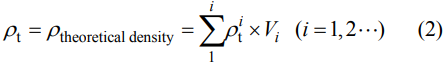
In general, indentation fracture toughness is influenced by the elastic modulus, indentation characteristics, and the internal stress field. The toughening mechanism is often manifested as the change of crack propagation path and the shielding effect of crack tip [73]. In this work, the possible reasons for the increase of fracture toughness are: the increase of elastic modulus, crack pinning, crack bridging, crack deflection, and crack branching, as shown in Fig. 13. First, the increase of elastic modulus is beneficial to the increase of indentation fracture toughness. Because when the elastic modulus is large, the driving force (strain energy release rate) for crack expansion is small. In order to advance the crack and destroy the specimen, a larger strain energy release rate is bound to be applied [74]. As a result, fracture toughness increases. Second, a crack pinning toughening mechanism was present in the low alumina composition sample (AS70) (Fig. 13(a)). This is because when the crack extends to the equiaxed corundum dendrites, the energy of crack extension is effectively absorbed to achieve the toughening effect. However, this toughening effect is limited, as the fracture toughness only increased from 1.95 to 2.15 MPa·m1/2 for samples AS70 and AS80 (Fig. 12). Third, with the increase of alumina content in the initial powder, the corundum morphology in the melt-grown AMC evolved from near-equiaxed dendrites to columnar or cellular structures, and more alumina grains were precipitated, which is beneficial for crack deflection to consume the fracture energy (Fig. 13(b)), resulting in a gradual increase of fracture toughness. Because corundum grains with rod (large aspect ratio) morphology have the highest efficiency for the toughness [75]. Fourth, crack bridging is very common in the samples of different compositions (not fully shown in this paper), and some cracks showed nearly linear morphology in corundum grains (Fig. 13(c)). The internal friction between the near-linear bridging cracks contributes to the increase of toughness [76]. In addition, crack branching increases the fracture toughness by increasing the crack propagation energy, which was also observed in this study (Fig. 13(b)). Finally, the decrease in fracture toughness of AS95 sample can be attributed to the increase in grain size. The significant increase in grain size of AS95 sample compared to AS90 and AS92.5 samples (especially the statistical results of the cross section) is due to the presence of a small amount of liquid phase that promotes the anisotropic growth of corundum grains [77]. In this study, the grain size of AS95 sample was in the micron scale (~23–31 μm). The fracture toughness of the melt-grown AMC at this scale decreased with increasing grain size, which is related to the thermal expansion anisotropy and internal stress of corundum grains [78]. Moreover, the addition of trace silica contributes to the formation of mullite with a low coefficient of expansion, and the formation of mullite is excellent for enhancing the fracture toughness of the composite. As shown in Fig. 12, for sample AS92.5, at this point, the initial powder contains 7.5 mol% silica and 92.5 mol% alumina. The silica content more excellent or less than this ratio will reduce the fracture toughness of the composite.
Fig. 13 Toughening mechanism of the melt-grown AMC: (a) AS70, (b) AS90, and (c) AS92.5.
3.2.4 Flexural strength
Figure 14 shows the flexural strength of the melt-grown AMC measured using the three-point bending method as a function of the initial composition. With the increase of alumina content in the initial powder, the flexural strength increased from 34.3±6.7 MPa to the highest value of 310.1±36.5 MPa. On the one hand, for samples with less than 95 mol% alumina in the initial powder (AS70, AS80, AS90, and AS92.5), the presence of mullite and corundum was confirmed by XRD (Fig. 6) and TEM (Fig. 7). The highest flexural strength of the melt-grown AMC is higher than that of melt-grown alumina ceramics (~210 MPa [79]) prepared by the same method and more than twice that of the melt-grown mullite ceramics (~62.8 MPa [37]). The flexural strength of the AMC prepared by different methods is significantly different (Table 4). Among them, the flexural strength of the AMC prepared by traditional sintering methods is generally low due to poor purity, defects, and large grain size [66,69–72]. The flexural strength of 300 MPa and above is possible only when the grain size reached 2–4 μm [13]. The melt-grown AMC prepared by reaction sintering and spark plasma sintering have higher flexural strength because of the smaller grain size (2.2±0.36 μm for reaction sintering [10] and 0.24±0.05 μm for spark plasma sintering [67]). On the other hand, the flexural strength was significantly increased for the sample AS95 compared to the other samples with low alumina composition. XRD and TEM confirmed that the corundum grains in the AS95 sample were in the glass phase (~2.1 vol%) between the grains, rather than mullite. The possible reason for the significant increase in the flexural strength of the sample AS95 is the glass phase’s presence. The factors influencing the strength of composites are analyzed in detail below.

Fig. 14 Flexural strength of the melt-grown AMC.
According to Griffith’s strength theory:

where σf is the strength, E is the elastic modulus, γf is the fracture surface energy used to describe the energy consumed per unit area of crack propagation in a material, and a is the crack size. It can be seen that the strength of ceramic materials depends on three parameters, elastic modulus, fracture surface energy, and crack size. Therefore, in this study, the possible reasons for the increase in flexural strength of composites are as follows: (1) the reduction of defects (cracks and pores); (2) the increase of elastic modulus and the change of fracture mode; (3) the reduction of internal residual stress.
First, compared with pores, cracks are more likely to cause the AMC fracture. Figure 15 shows the typical morphology of cylindrical samples and cuboid samples with different compositions, where the cylindrical samples were prepared directly using the DLD technology. These cuboid samples for the three-point bending test were obtained by simply grinding the surface of the cylindrical samples using diamond discs, without further pressing them. The cuboid samples were not directly prepared using the DLD technology to evaluate the flexural strength in this study. This is because the three-point bending standard requires strict sample dimensions, e.g., 3±0.2 mm for the thickness and 4±0.2 mm for the height of a cubical structure; however, the accuracy of melt-grown ceramics prepared by DLD is currently far from this level, usually ±1 mm. Therefore, samples conforming to the three-point bending standard cannot yet be prepared directly using the DLD technique. Moreover, the accuracy control is still a big challenge in shaping melt-grown ceramics using the DLD technique as far as the current study is concerned. However, it is still possible to use this technique to shape ceramic structures with maximum cross-sectional dimensions of about 20 mm (e.g., vane, cone, and pyramid) and long rods whose length is limited by the machine tool [80]. The preparation of structural parts with larger cross-sections is a limitation of the technique due to tensile stresses inside the samples. For the cylindrical samples (Fig. 15), no obvious macroscopic cracks were found on the surface of the cylindrical samples with different compositions. Moreover, the cylindrical samples were about 6 mm in diameter, and there was no apparent pattern influence of the composition on the roughness of the sample surface. However, after careful grinding (no pressing required) of the cylindrical sample into a cuboid sample used to evaluate the flexural strength, multiple transverse cracks and some longitudinal cracks appeared on the surface of sample AS70. The complex crack morphology may be due to the low elastic modulus of the sample with this composition (Fig. 10), which tends to form cracks during the fabrication of the cuboid samples. The presence of these cracks makes the flexural strength of the sample AS70 to be the lowest. Similarly, the longitudinal crack remained inside the AS80 cuboid samples and fewer transverse cracks, resulting in a higher strength than that of the AS70 samples. Therefore, the flexural strengths of AS70 and AS80 were lower than those of the previous melt-grown mullite ceramics. In comparison, other cuboid samples with high alumina content (e.g., AS90, AS92.5, and AS95) did not have significant macroscopic cracks. The relationship between their strength and composition may be related to other factors.

Fig. 15 Morphology of cylindrical samples (left) and cuboid samples (right).
In addition, the overall strength of the AMC can also be explained by the empirical relationship of strength/porosity [17,81–83]:

where σ0 is the strength of composites when porosity is 0, P is the porosity of the samples, and n is a constant. The presence of pores greatly reduced the strength of the AMC, as shown in Fig. 16. With the increase of alumina content in the initial powder, the porosity decreased, and the relative density increased, improving the strength. In particular, for sample AS70, there were pores visible to the naked eye at the end of the cuboid sample (Fig. 15), which is not conducive to the densification of the sample AS70. Moreover, for AS95, a small amount of liquid phase due to the addition of trace silica was completely infiltrated the corundum grains (Fig. 7), promoting the densification of the AMC [55].
In conclusion, we further evaluated the size of the initial flaw in the samples of the melt-grown AMC with different compositions. For an unstable crack system, the critical flaw size is obtained from Eq. (16) [84,85]:

where KIC is the fracture toughness, which is the average value of the cross section and longitudinal section of the samples, σf is the fracture strength, and Y is a geometric factor, which is related to the geometry and location of the crack, the acting mode of external stress, and the geometry and size of the fracture sample. For the half-penny crack, Y = 2/π; for the semi-elliptical surface defects, Y = 1.12. This paper used Y = 1.12 to evaluate the Griffith critical flaw size. The calculation results are shown in Table 5.


Fig. 16 Relationship between flexural strength and porosity. Reproduced with permission from Ref. [61], © The American Ceramic Society 1987.
Table 5 Critical flaw size and fracture surface energy for the melt-grown AMC determined by Griffith fracture criterion

It can be found that the critical flaw size decreases with increasing alumina content in the initial powder. Moreover, the closer alumina content to the mullite ratio, the larger the defect size. The reduction of critical flaw size is beneficial to improving composite strength. With the increase of alumina content in the initial powder, the critical flaw size gradually decreases, which is beneficial to the strength of the AMC.
Second, the elastic modulus of the melt-grown AMC gradually increases with the increase of alumina content in the initial powder, as shown in Fig. 10. According to Eq. (9), it is obvious that the increase in elastic modulus is beneficial to increasing the strength. The strength of the AMC gradually increases with the increase of alumina content. For the sample AS70 with less corundum precipitation, the resistance to external forces is mainly supported by the mullite phase. Although sample AS70 also exhibits transgranular fracture (Fig. 17(a)), the composite has lower strength due to the low elastic modulus of mullite. With the increase of corundum precipitation, the fracture morphology gradually appears as a paste (Fig. 17(b)), intergranular + transgranular fracture (Figs. 17(c) and 17(d)), and transgranular fracture (Fig. 17(e)). The evolution of the fracture mode from mullite transgranular fracture to corundum transgranular fracture increases the fracture surface energy of the composites. Specifically, the variation of fracture surface energy with fracture mode was evaluated according to Eq. (17) [86,87], as shown in Table 5. The fracture surface energy ( γf ) of the composite material was calculated. The fracture surface energy of the composites tended to increase with the increase of alumina content in the initial powder. However, the sample AS95’s fracture surface energy did not increase significantly but decreased compared to that of AS92.5. This is caused by the increase of the elastic modulus, as shown in Eq. (14). However, the increase in the overall strength of the composites is attributed to the increase in the sample density (a decrease in porosity, as shown in Table 3) and a significant decrease in the critical flaw size (Table 5).

Fig. 17 Three-point bending fracture morphology of the melt-grown AMC: (a) AS70, (b) AS80, (c) AS90, (d) AS92.5, and (e) AS95.
Third, the thermal expansion coefficients of corundum and mullite are not consistent, where corundum is 4.48×10⁻⁶ K-1 [12] and mullite is 8.79×10⁻⁶ K-1 [15]. As a result, residual stress is easy to form in the AMC [88,89]. At the end of sample shaping, the sample cooled and contracted, and internal stress will be generated at the phase interface due to the strain mismatch caused by thermal expansion and elasticity. As internal stresses (tensile or compressive stress) reduce the fracture surface energy of the AMC, microcracks are formed at the interface or inside the grain [73], reducing the material strength (Eq. (9)). The phase interface stress of the microstructure can be evaluated qualitatively by Eq. (18) proposed by Zhang et al. [89] and Selsing [90], where m and a refer to the continuous mullite matrix and corundum phase, respectively. It can be seen from Eq. (18) that the residual stress decreases with the increase of corundum content in the composites. The reduction of residual stresses is beneficial for reducing the number of cracks in the composites. In particular, for sample AS95, there is only a corundum phase and a small amount of glass phase. The glassy phase compensates for the internal stresses due to the different thermal expansion coefficients and the contact of facet corundum grains [55]. This may have reduced the residual stress inside the sample.
4 Conclusions
In this work, dense high-performance melt-grown alumina–mullite/glass composites were prepared by in situ synthesis of alumina and silica powder using DLD technology. The microstructural characteristics of the samples prepared with different initial compositions were investigated, and the strengthening and toughening mechanisms of the composites were analyzed. The research results provide a novel approache and insight for the rapid preparation of high-performance melt-grown composites, which has significant application in the preparation of materials for hot-end components and thermal protection systems. The main conclusions are as follows:
(1) When the alumina content in the initial powder was low (70 mol%), the microstructure was composed of discrete corundum, continuous mullite, and glass phase, and the corundum grains were near-equiaxed dendrite. With the increase of alumina content, nearequiaxed dendrite gradually evolved into columnar dendrite structures and cellular structures due to the weakening of the constitutional supercooling and the small nucleation undercooling at the solid–liquid interface. Sample AS95 was composed of corundum and glassy phase, possibly because silicon-containing melts fail to form a glass phase under rapid cooling conditions. At the interface of two phases, the corundum grains were facet, reducing the residual stress. The glass was wholly infiltrated on the surface of corundum grains, which effectively promotes the compactness.
(2) High-performance melt-grown alumina–mullite/glass composites with high densification (< 99.4%) and low porosity (≥ 0.63%) can be prepared by the DLD technology. With the increase of alumina content in the initial powder, the density gradually increased (3.93 g/cm³), and the porosity gradually decreased. The microhardness and fracture toughness of the composites showed a parabolic pattern with a large increase followed by a small decrease. The highest microhardness and fracture toughness reached 18.39±0.38 GPa and 3.07± 0.13 MPa·m1/2, respectively, which were significantly higher than those of the same material prepared by the traditional sintering method because of the growth characteristics of single crystal fiber in the microstructure. The flexural strength increased with the increase of alumina content, and the maximum value was 310.1± 36.5 MPa when the alumina content was 95 mol%. This strength value is 47.7% higher than that of melt-grown alumina ceramics. And the best flexural strength belongs to the alumina/glass composites without mullite. The microhardness and fracture toughness are still lower than those of pure alumina ceramics prepared by the same method.
(3) The microhardness of alumina–mullite/glass composites increased significantly due to the increase of relative density and corundum precipitation. The small decrease is attributed to the increase of grain size of corundum in the liquid phase. The increase in fracture toughness of the composites is due to the increase in elastic modulus, crack pinning, crack bridging, crack deflection, and crack branching. The increase in flexural strength resulted from the decrease in defects (cracks and pores), the increase in elastic modulus, the change in fracture pattern, and the decrease in internal residual stress.
Reference: Omitted
Declaration: This article is provided by CERADIR™ users or obtained from Internet, the content does not represent the position of CERADIR™. We are not responsible for the authenticity/accuracy of the article, especially the effects of the products concerned. This article is for study only, it does not constitute any investment or application advice. For reprinting, please contact the original author. If it involves the copyright and/or other issues, please contact us and we will deal with it asap! CERADIR™ has the interpretation of this declaration.