Abstract: Porous three-dimensional SiC/melamine-derived carbon foam (3D-SiC/MDCF) composite with an original open pore structure was fabricated by the heat treatment of the commercial melamine foam (MF), carbonization of the stable MF, and chemical vapor deposition of the ultra-thin SiC coating. Scanning electron microscopy (SEM) and X-ray diffraction (XRD) were employed to detect the microstructure and morphology of the as-prepared composites. The results indicated that the 3D-SiC/MDCF composites with the coating structure were prepared successfully. The obtained minimum reflection loss was –29.50 dB when the frequency and absorption thickness were11.36 GHz and 1.75 mm, respectively. Further, a novel strategy was put forward to state that the best microwave absorption property with a thin thickness of 1.65 mm was gained, where the minimum reflection loss was –24.51 dB and the frequency bandwidth was 3.08 GHz. The excellent electromagnetic wave absorption ability resulted from the specific cladding structure, which could change the raw dielectric property to acquire excellent impedance matching. This present work had a certain extend reference meaning for the potential applications of the lightweight wave absorption materials with
target functionalities.
Keywords: three-dimensional SiC/melamine-derived carbon foam (3D-SiC/MDCF); chemical vapor deposition; coating structure; electromagnetic wave absorption characteristic; minimum reflection loss
1 Introduction
Environmental and energy concerns were urgent issues that human beings needed to solve nowadays [1–3]. With the rapid development of the electromagnetic wave technology, various electromagnetic interference (EMI) had threatened to the normal operation of the electronic equipment in the complex industrial environment. The wide application of microwave technology (television, mobile phones, radio) and electronic technology greatly increased the electromagnetic radiation and posed many potential hazards. Hence, the effective microwave absorption materials had attracted ever-increasing attention [4–10]. In general, the reasonable impedance matching and electromagnetic wave attenuation capability had become the key factors in the successful design of the excellent microwave absorption materials, where poor impedance matching characteristics led to low reflection loss and weak attenuation resulted in unsatisfactory behaviors [9,11]. Moreover, the electromagnetic absorption properties also depended on the microstructure, geometry, and morphology [12–14]. In the past decade, lightweight absorbing materials such as magnetic/carbon composites [15], core–shell structures [16], and hollow structures [17] had been developed to meet the needs of practical applications.
Among these structures, three-dimensional (3D) lightweight materials with macroscopic porous were considered as one of the most likely candidates, associated with the basic properties characteristic of carbon materials for high-performance broadband microwave absorption applications [4,18–20]. The microwave absorption foam possessed a lower bulk density and smaller effective permittivity due to the open pore structure [21]. Hence, many researchers focused on the porous bulk materials such as carbon nanotube sponge [22], carbon foam (CF) [23,24], silicon carbide (SiC) foam [25,26], and conductive polymer foam [27,28]. However, the performances of the most microwave absorption foams reported previously were much lower than the conventional one. Besides, the preparation process of the microwave absorption foams was time-consuming and complicated, which further restricted its scope of application. Chen et al. [29] studied the metal-containing foam glass consisting of zinc oxide, zinc, and foam glass by sintering mixture of zinc powder and foam glass material, and the zinc-containing foam glass with zinc filler could obtain the minimum reflectivity of –15.6 dB. He and Gong [30] prepared the foam-based honeycomb sandwich structures with magnetic metal micropowder and carbonyl iron/nickel fibers via a foaming technique. The minimum reflection loss was –26 dB. Wang et al. [31] reported the 3D structure CF using coal liquefaction residue as the carbon source. The results showed that the impregnated polyurethane foam after being carbonized at 750 ℃ showed the best microwave absorption value of almost –12.5 dB. Song et al. [32] designed the in-situ grown ZnO nanowires enhanced reduced graphene oxide foams through a direct freeze-drying and hydrothermal process. It possessed a minimum reflection loss value of –27.8 dB.
Besides, the material type of the microwave absorber also had an obvious effect on the electromagnetic properties. SiC, a kind of remarkable microwave absorption materials, had been widely investigated due to the good mechanical strength, excellent chemical resistivity, high thermal stability, and low density [33–35]. However, the dielectric properties were too poor to be used as an ideal microwave absorption material, which resulted from the low conductivity and the single polarization [36,37]. To overcome this deficiency, multiple SiC-based materials had been developed such as SiC nanowires [38], SiC particles [39], SiC fiber reinforced SiC matrix composites [40], and elements doped SiC particles [41], which possessed excellent microwave absorption properties under harsh environmental conditions. Xiao et al. [42] prepared the hybrid foams nanostructured with SiC nanowires and lamellar carbon films by the freeze-drying and carbonization techniques. The results showed that the composites possessed outstanding electromagnetic absorbance characteristics, which could be applied in information countermeasures, weapon systems, and contemporary electronics. Li et al. [43] fabricated the ferrocene-modified polycarbosilane composite ceramics. Crystallized carbons including graphene-like carbons, onion-like carbons, turbostratic carbons, and carbon nanowires were detected. The real and imaginary permittivities of the SiC/C composite were improved greatly. Dong et al. [44] designed the core–shell SiCw@C heterostructures with higher tunability and better microwave via a hydrothermal and carbonization process. The whole Ku-band and X-band were covered by adjusting the sample thickness of the SiCw@C heterostructures coated with carbon shell, which could be used in military and civilian fields.
Consequently, a simple method to produce porous 3D-SiC/MDCF composites was introduced for the first time in this article, which was highly considered as a lightweight electromagnetic wave absorbing material. The commercial melamine foam (MF) with high porosity (~96%) was used to fabricate the open-cell melamine derived carbon foam (MDCF), which acted as the electromagnetic shielding precursor. An ultra-thin SiC film was then deposited using the chemical vapor deposition (CVD) technology to manufacture porous 3D-SiC ceramics with a net-like structure. The effects of the SiC coating on the microstructure and microwave absorption properties of the as-prepared samples were studied at last.
2 Experimental procedures
2. 1 Fabrication process
The 3D-SiC/MDCF composite was manufactured by the following steps as shown in Fig. 1 [45,46]. MF with a low density ranging from 6 to 9 kg/m³ was purchased from Zhongyuan Dahua Group Co., Ltd., Henan, China. However, the primary MF was instable with residual molecules, which directly determined the performance of the final composite. Hence, the first heat treatment step (I) was to place MF into the vacuum tube furnace and then annealed at a relatively low temperature of 200 ℃ at N2 atmosphere for 5 h to get the stable MF. Subsequently, the samples were heated to 1100 ℃ at the ramping rate of 1 ℃/min during the carbonization stage (II). It was an effective way to prevent the gas cavity and severe skeleton deformation by annealing at a low heating rate. After keeping warm for 5 h, the CVD technique was employed to deposit SiC film on the surface of the MDCF skeleton. Argon, hydrogen, and methyltrichlorosilane were used as the dilution gas, the reactant gas, and the
SiC precursor with the gas flow ratio of 140:280:30.

Fig. 1 Fabrication procedure of 3D-SiC/MDCF composite.
Finally, the as-prepared 3D-SiC net structure was formed on the surface, and the 3D-SiC/MDCF composites were obtained. Especially, the original structure of MDCF acted as the skeleton template, and the ultra-thin SiC coating grew along the outer wall of the skeleton, which resulted in the formation of the 3D-SiC/MDCF composites. As a control experiment, the 3D-SiC/ MDCF composites with different deposition time (8 and 16 h) were prepared, which were denoted as 3D-SiC/MDCF-I and 3D-SiC/MDCF-II, respectively.
2. 2 Characterization
The scanning electron microscopy (SEM) overviews were obtained by JEOL JSM-6360. The X-ray diffraction (XRD) patterns were detected by the Rigaku D/max 2550 X-ray diffractometer with a 2θ scope of 5°–80°, which provided information on phase components and crystallinity. The permittivity of the samples with the transmission method for the simulation of reflection loss was tested by a vector network analyzer (Agilent, N5244A), and the measured frequency was limited in 2–18 GHz. The 3D-SiC/MDCF composites were homogeneously mixed with paraffin wax which was selected as 40 wt%, and then shaped into the toroidal measured samples with the outer diameter of 7.0 mm and the inner diameter of 3.0 mm.
3 Results and discussion
3. 1 Evolution of 3D-SiC/MDCF structure
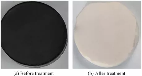
The evolution progress of the as-prepared samples was illustrated in Fig. 2(a). After the complete pyrolysis, a great volume shrinkage took place obviously as the white MF with the specified size of ~6.5 cm × 3.5 cm× 2.0 cm was converted into the black MDCF with the size of ~3.1 cm × 1.7 cm × 1.0 cm, which had attracted considerable interest as a promising electromagnetic wave absorber due to the great chemical stability, large surface, and open cell wall structure. However, the appearance and shape features of 3D-SiC/MDCF did not change obviously after the CVD process as shown in Fig. 2(a). As for the microstructures of MF, MDCF, 3D-SiC/MDCF in Figs. 2(b)–2(d), MF possessed the 3D open-hole structure, consisting of the junctions and the chain links between the junctions, which determined the novel characteristics such as lightweight, large geometric surface area, high thermal and electrical conductivities, hydrophobic surface nature, and high thermal stability [47]. MDCF maintained the original structure of MF in large part except for the pore structure. Moreover, 3D-SiC/MDCF also inherited the 3D network, in which most of the macro-pores were interconnected.

Fig. 2 Evolution progresses of MF, MDCF, and 3D-SiC/MDCF: (a) overview images of samples; microstructures of (b) MF, (c) MDCF, and (d) 3D-SiC/MDCF.
The corresponding XRD patterns of the MDCF, 3D-SiC/MDCF-I, and 3D-SiC/MDCF-II samples were detected to confirm the deposition of the SiC films. Figure 3 shows that MDCF was a kind of amorphous material with no obvious diffraction peaks except two weak peaks near the planes (002) and (111) [48]. After the CVD process, the strength of the amorphous peaks decreased, and three great diffraction peaks appeared at 35.6°, 59.9°, and 71.5° which matched well with (111), (220) and (311) reflections of the crystal faces of β-SiC [49]. Besides, the changes of the apparent densities of the samples in a certain degree further demonstrated the deposition of the ultra-thin SiC coating. The densities of MF and MDCF were 6.82 and 6.21 kg/m³, respectively. However, the densities of 3D-SiC/MDCF-I and 3D-SiC/MDCF-II were 14.51 and 20.19 kg/m³, respectively, which were much higher than that of MF and MDCF.

Fig. 3 XRD spectra of MDCF, 3D-SiC/MDCF-I, and 3D-SiC/MDCF-II.
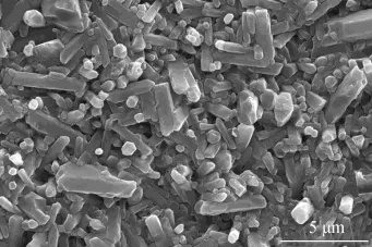
Figures 4(a)–4(c) shows the microstructures of the MDCF, 3D-SiC/MDCF-I, and 3D-SiC/MDCF-II samples under high magnification. The microstructures of the junctions of MDCF are illustrated in Fig. 4(a), which shows a smooth surface with some drawbacks. During the CVD process, SiC particles were attached to the surface of the MDCF skeleton and increased the surface roughness. The rough surface was obtained as the countless SiC nanoparticles were deposited on the original skeleton in Fig. 4(b). Also, CVD technology led to a remarkable increase in both the cross-section areas of the junctions and the chain links. With the increase of the deposition time, the surface became much coarser as shown in Fig. 4(c). It was worth mentioning that this cladding structure and the agglomerated particles were beneficial to the enhancement of electromagnetic wave absorption. In addition, Fig. 4(d) displays the energy-dispersive X-ray spectrometer of Si and C in the agglomerated particles in Fig. 3. It was noted that the rough surface caused by the CVD technology was beneficial to the microwave absorbing.

Fig. 4 Microstructure characterization of (a) MDCF, (b) 3D-SiC/MDCF-I, (c) 3D-SiC/MDCF-II under high magnification, and (d) energy-dispersive X-ray spectrometer of agglomerated particles.
3. 2 Electromagnetic property
The electromagnetic wave absorbing performances were largely determined by the relative complex permittivity and permeability, and the imaginary parts (ε″ and μ″) were associated with the dissipation of electric and magnetic energy while the real parts of the relative complex permittivity and permeability (ε′ and μ′) denoted the storage capacity of electric and magnetic energy [50]. In this work, the test results showed that μ′ and μ″ ranged with a slight fluctuation where μ′ ≈ 1.0 and μ″ ≈ 0.0, which indicated that the complex permeability did not have much to do with the measured frequency [51]. Hence, the complex permeability was ignored, and we only focused on the variation of the complex permittivity. Figures 5(a) and 5(b) display the relationship between the relative complex permittivity and the certain range of the frequency for the MDCF, 3D-SiC/MDCF-I, and 3D-SiC/MDCF-II samples. The values of ε′ and ε″ showed a downward trend with the increasing of the measured frequency. For the MDCF sample, the ε′ and ε″ values were much higher, which indicated that MDCF possessed a higher electrical conductivity, resulting in a lower impedance mismatching and limiting its electromagnetic wave absorption property [52]. On the contrary, the ε′ and ε″ values of the 3DSiC/MDCF composites were relatively lower, especially the ε′ value of 3D-SiC/MDCF-II. The curve fluctuation of the relative complex permittivity in the relatively higher frequency of 16–18 GHz was in consequence of the resonance effect. The results revealed that the 3D-SiC coating had significantly impacted the permittivity and then the final electromagnetic wave absorbing performance. It was obvious that the differences between ε′ and ε′′ varied with the deposition time, which manifested that the content of SiC had a crucial relation to the complex permittivity. Besides, the dielectric loss was suggested to result from the interfacial polarizations [48] which originated from the existence of countless micro interfaces among the MDCF skeleton, 3D-SiC coating, and air. New interspaces, as well as the agglomerated particles formed by the CVD process, improved interfacial polarization and led to the dielectric loss.

Fig. 5 Real part (a) and imaginary part (b) of the permittivity of MDCF, 3D-SiC/MDCF-I, and 3D-SiC/ MDCF-II.
The multiple peaks in Fig. 5 indicated the resonance behaviors, most of which were relevant to the interface polarization. It was ascribed to the great difference in electrical conductivity among the MDCF skeleton and SiC coating [53]. Figure 6 shows the Cole-Cole plots of the MDCF, SiC/MDCF-I, and 3D-SiC/MDCF-II composites based on the Debye theory. As we could see, the plots of SiC/MDCF-I and 3D-SiC/MDCF-II were much more complex as several single semicircles appeared due to the multi-interfaces between the SiC coating and MDCF skeleton [54]. In general, the polarization ability of a material mainly consisted of the interfacial polarization and dipolar polarization at the microwave frequency [55]. The surface defect, skeleton fracture, and interface crack might result in the increase of dipole amount, which formed the dipole polarization. However, the weak dipole polarization had a very small influence on polarization loss.

Fig. 6 Cole-Cole plots of MDCF, SiC/MDCF-I, and 3D-SiC/MDCF-II.
It had been proved that the dielectric loss promoted the excellent microwave absorption performance. δε was defined as the tangent of the dielectric loss angle,
which could be expressed as [56]:
tan δε = ε′′/ ε ′ (1)
Figure 7 shows the tanδε of the composites versus frequency with different deposition time. The values of ε″ of 3D-SiC/MDCF-I and 3D-SiC/MDCF-II were almost the same, while the values of ε′ of 3D-SiC/MDCF-I was much higher than that of 3D-SiC/MDCF-II, which resulted in the decrease of tanδε. Hence, tanδε increased with the SiC coating depositing ratio at different frequencies as shown in Fig. 7, and each curve had several relaxation
peaks over the tested frequency range.

Fig. 7 Dielectric loss tangents of 3D-SiC/MDCF-I-wax and 3D-SiC/MDCF-II-wax composites.
In addition to the dielectric loss, the appropriate matching of the dielectric and magnetic properties also determined the absorption capabilities, which could be characterized by the reflection loss (RL) of the resultant 3D-SiC/MDCF composites. Zin was the input impedance in the air to the absorber surface, and the expressions were as follows [57]:

where c is the velocity of light, d is the thickness of the absorber, Z0 is the impedance of free space, εr is the permeability defined as ε′–jε″, and μr is the relative complex permeability, which is calculated by μ′–jμ″.
Figure 8 shows the reflection loss of the porous 3D-SiC/MDCF-II composite with the thicknesses of 1.65,1.75, 1.85, and 1.95 mm. The lowest reflection loss of –29.50 dB was obtained when the absorber layer thickness was 1.75 mm, and the effective frequency bandwidth was 2.64 GHz (Fig. 8(b)). However, there were clear variations in the minimal reflection loss as well as the effective bandwidth when the absorber layer thickness changed (Figs. 8(a), 8(c), and 8(d)). The minimal reflection loss was –24.51 dB and the effective frequency bandwidth was 3.08 GHz for the absorber thickness of 1.65 mm. With the absorber layer decreasing in thickness, both the minimal reflection loss and effective bandwidth increased. However, the minimal reflection loss increased to –25.96 dB and the effective bandwidth decreased to 2.40 GHz when the thickness was 1.85 mm, which showed a reverse trend. Based on this phenomenon, a novel strategy was proposed to judge the optimum thickness where the electromagnetic wave absorption properties were the best [58]. The value of ΔS was defined as the area of the shaded part when the reflection loss was less than –10 dB, and RE was defined as ΔS/d which presented electromagnetic absorption efficiency. The theory behind this was that for common applications, the reflection loss of the microwave absorbing material should be less than the general requirements of –10 dB, which implied that more than 90% of the electromagnetic energy was absorbed and less than 10% was reflected. Hence, the calculation formula of ΔS was as follows:


Fig. 8 Reflection loss of porous 3D-SiC/MDCF-II-wax composites with various thicknesses: (a) 1.65, (b) 1.75, (c) 1.85, and (d) 1.95 mm.
Hence, the corresponding ΔS values were 48.75, 46.34,39.93, and 32.58 dB·GHz when the absorber layer thicknesses were 1.65, 1.75, 1.85, and 1.95 mm, respectively. Then RE values for the absorber thicknesses of 1.65, 1.75, 1.85, and 1.95 mm were 29.55, 26.48, 21.58, and 16.71 dB·GHz·mm−1, respectively. By numerical computation, the optimal electromagnetic wave absorption was deduced with the absorber thickness of 1.65 mm.
Based on Eqs. (2) and (3), the thickness of the absorber was the most important factor to influence the input impedance and then affect the reflection loss values of the electromagnetic wave among all the factors. In this article, the porous 3D-SiC/MDCF composites with various thicknesses were tested to study the influence of the thickness. The 3D-SiC/MDCF paraffin-based composites with various thicknesses were prepared, and the results are exhibited in Fig. 9. The reflection loss was reduced to a minimum value of –29.55 dB at 11.36 GHz for the absorber thickness of 1.75 mm. What was more remarkable was that when the frequencies ranged from 3.36 to 18.0 GHz and the thickness ranged from 1.05 to 5.0 mm, the absorber with the reflection loss values less than 10 dB could be obtained which provided guidance on the structural design.

Fig. 9 3D representation of reflection loss values for the 3D-SiC/MDCF-II-wax composite.
The porous 3D-SiC/MDCF composites had great potential in a wide frequency range due to the properties of the vesicular structure, lightweight, and strong absorption. The excellent absorption performance of electromagnetic waves resulted from the micro gap
between the SiC coating and the MDCF skeleton as well as the agglomerated particles, which improved the multiple reflections and scatterings. The propagation distance of the electromagnetic wave was prolonged, and much of the wave energy was converted into heat energy [59].
4 Conclusions
In summary, the excellent microwave-absorbing 3DSiC/MDCF composites were synthesized successfully in this work, and some conclusions were as follows:
(1) The fabrication process of this porous 3D-SiC/MDCF composites consisted of the heat treatment, carbonization, and CVD process, which inherited the original architecture intact and increased the contact interfaces. SEM and XRD further confirmed the deposition
of the ultra-thin SiC coating, which was considered to be favorable for the microwave absorption.
(2) CVD deposition time had a marked impact on the surface of the MDCF skeleton, which further affected the microwave absorption property. The permittivity of the 3D-SiC/MDCF-II was much lower than that of 3D-SiC/MDCF-I. The outstanding microwave absorption abilities were ascribed to the cladding structure and the agglomerated particles.
(3) The minimal reflection loss of 3D-SiC/MDCF-II was –29.65 dB, which was obtained at the absorbent thickness of 1.75 mm. Furthermore, the reflection loss values less than –10 dB could be obtained in a wide frequency ranging from 3.34 to 18 GHz when the absorber thicknesses were between 1.05 and 5.0 mm. The results demonstrated that the porous 3D-SiC/MDCF composites were potentially lightweight excellent absorbing material.
Acknowledgements
The present work was supported by the National Natural Science Foundation of China (Grant Nos. 51772151 and 51761145103) and the Priority Academic Program Development of Jiangsu Higher Education Institutions.
References
[1] Chen Z, Chen ZF, Yang ZG, et al. Preparation and characterization of vacuum insulation panels with superstratified glass fiber core material. Energy 2015, 93: 945–954.
[2] Tang J, Meng HM, Huang LL. Energy-saving and environmentally friendly electrodeposition of γ-MnO2. RSC Adv 2014, 4: 16512–16516.
[3] Chu S, Majumdar A. Opportunities and challenges for a sustainable energy future. Nature 2012, 488: 294–303.
[4] Chen ZP, Xu C, Ma CQ, et al. Lightweight and flexible graphene foam composites for high-performance electromagnetic interference shielding. Adv Mater 2013, 25:1296–1300.
[5] Duan WY, Yin XW, Li Q, et al. A review of absorption properties in silicon-based polymer derived ceramics. J Eur Ceram Soc 2016, 36: 3681–3689.
[6] Li Q, Yin XW, Duan WY, et al. Electrical, dielectric and microwave-absorption properties of polymer derived SiC ceramics in X band. J Alloys Compd 2013, 565: 66–72.
[7] Duan WY, Yin XW, Luo CJ, et al. Microwave-absorption properties of SiOC ceramics derived from novel hyperbranched ferrocene-containing polysiloxane. J Eur Ceram Soc 2017, 37: 2021–2030.
[8] Wang P, Cheng LF, Zhang LT. One-dimensional carbon/SiC nanocomposites with tunable dielectric and broadband electromagnetic wave absorption properties. Carbon 2017,125: 207–220.
[9] Wen B, Cao MS, Hou ZL, et al. Temperature dependent microwave attenuation behavior for carbon-nanotube/silica composites. Carbon 2013, 65: 124–139.
[10] Zhong B, Sai TQ, Xia L, et al. High-efficient production of SiC/SiO2 core-shell nanowires for effective microwave absorption. Mater Des 2017, 121: 185–193.
[11] Liang XH, Quan B, Ji GB, et al. Novel nanoporous carbon derived from metal–organic frameworks with tunable electromagnetic wave absorption capabilities. Inorg Chem Front 2016, 3: 1516–1526.
[12] He S, Wang GS, Lu C, et al. Controllable fabrication of CuS hierarchical nanostructures and their optical, photocatalytic, and wave absorption properties. ChemPlusChem 2013, 78: 250–258.
[13] Yuan XY, Cheng LF, Guo SW, et al. High-temperature microwave absorbing properties of ordered mesoporous inter-filled SiC/SiO2 composites. Ceram Int 2017, 43:282–288.
[14] Wang P, Cheng LF, Zhang YN, et al. Flexible, hydrophobic SiC ceramic nanofibers used as high frequency electromagnetic wave absorbers. Ceram Int 2017, 43:7424–7435.
[15] Li GM, Wang LC, Li WX, et al. CoFe2O4 and/or Co3Fe7 loaded porous activated carbon balls as a lightweight microwave absorbent. Phys Chem Chem Phys 2014, 16:12385–12392.
[16] Zhao B, Shao G, Fan BB, et al. Fabrication and enhanced microwave absorption properties of Al2O3 nanoflakecoated Ni core–shell composite microspheres. RSC Adv 2014, 4: 57424–57429.
[17] Cheng Y, Guo YH, Zhang ZY, et al. Facile synthesis of NixCo3–xS4 hollow nanoprism with broader electromagnetic absorption properties: Effect of Ni/Co atomic ratios. J Alloys Compd 2018, 767: 323–329.
[18] Moglie F, Micheli D, Laurenzi S, et al. Electromagnetic shielding performance of carbon foams. Carbon 2012, 50:1972–1980.
[19] Zhang Y, Huang Y, Zhang TF, et al. Broadband and tunable high-performance microwave absorption of an ultralight and highly compressible graphene foam. Adv Mater 2015,27: 2049–2053.
[20] Kumar R, Dhakate SR, Gupta T, et al. Effective improvement of the properties of light weight carbon foam by decoration with multi-wall carbon nanotubes. J Mater Chem A 2013, 1: 5727–5735.
[21] Fang ZG, Cao XM, Li CS, et al. Investigation of carbon foams as microwave absorber: Numerical prediction and experimental validation. Carbon 2006, 44: 3368–3370.
[22] Crespo M, González M, Elías AL, et al. Ultra-light carbon nanotube sponge as an efficient electromagnetic shielding material in the GHz range. Phys Status Solidi RRL 2014, 8:698–704.
[23] Li Y, Shen B, Pei XL, et al. Ultrathin carbon foams for effective electromagnetic interference shielding. Carbon 2016, 100: 375–385.
[24] Yang J, Shen ZM, Hao ZB. Microwave characteristics of sandwich composites with mesophase pitch carbon foams as core. Carbon 2004, 42: 1882–1885.
[25] Zhu XW, Jiang DL, Tan SH. Microwave absorbing property of SiC reticulated porous ceramics. J Inorg Mater 2002, 17: 1152–1156. (in Chinese)
[26] Zhang HT, Zhang JS, Zhang HY. Computation of radar absorbing silicon carbide foams and their silica matrix composites. Comput Mater Sci 2007, 38: 857–864.
[27] Huang HD, Liu CY, Zhou D, et al. Cellulose composite aerogel for highly efficient electromagnetic interference shielding. J Mater Chem A 2015, 3: 4983–4991.
[28] Xie AM, Wu F, Sun MX, et al. Self-assembled ultralight three-dimensional polypyrrole aerogel for effective electromagnetic absorption. Appl Phys Lett 2015, 106:222902.
[29] Chen K, Li XH, Lv DS, et al. Study on microwave absorption properties of metal-containing foam glass. Mater Sci Eng B 2011, 176: 1239–1242.
[30] He YF, Gong RZ. Preparation and microwave absorption properties of foam-based honeycomb sandwich structures.Europhys Lett 2009, 85: 58003.
[31] Wang S, Xiao N, Zhou Y, et al. Lightweight carbon foam from coal liquefaction residue with broad-band microwave absorbing capability. Carbon 2016, 105: 224–226.
[32] Song CQ, Yin XW, Han MK, et al. Three-dimensional reduced graphene oxide foam modified with ZnO nanowires for enhanced microwave absorption properties. Carbon 2017, 116: 50–58.
[33] Chiu SC, Yu HC, Li YY. High electromagnetic wave absorption performance of silicon carbide nanowires in the gigahertz range. J Phys Chem C 2010, 114: 1947–1952.
[34] Liu HT, Cheng HF, Wang J, et al. Dielectric properties of the SiC fiber-reinforced SiC matrix composites with the CVD SiC interphases. J Alloys Compd 2010, 491: 248–251.
[35] Duan WY, Yin XW, Cao FX, et al. Absorption properties of twinned SiC nanowires reinforced Si3N4 composites fabricated by 3D-prining. Mater Lett 2015, 159: 257–260.
[36] Wu RB, Pan Y, Yang GY, et al. Twinned SiC zigzag nanoneedles. J Phys Chem C 2007, 111: 6233–6237.
[37] Duan WY, Yin XW, Li Q, et al. Synthesis and microwave absorption properties of SiC nanowires reinforced SiOC ceramic. J Eur Ceram Soc 2014, 34: 257–266.
[38] Wen LX, Ma YJ, Dai B, et al. Preparation and dielectric properties of SiC nanowires self-sacrificially templated by carbonated bacterial cellulose. Mater Res Bull 2013, 48:687–690.
[39] Li ZM, Zhou WC, Su XL, et al. Effect of boron doping on microwave dielectric properties of SiC powder synthesized by combustion synthesis. J Alloys Compd 2011, 509:973–976.
[40] Mu Y, Zhou WC, Hu Y, et al. Enhanced microwave absorbing properties of 2.5D SiCf/SiC composites fabricated by a modified precursor infiltration and pyrolysis process. J Alloys Compd 2015, 637: 261–266.
[41] Su XL, Zhou WC, Xu J, et al. Preparation and dielectric property of B and N-codoped SiC powder by combustion synthesis. J Alloys Compd 2013, 551: 343–347.
[42] Xiao SS, Mei H, Han DY, et al. Ultralight lamellar amorphous carbon foam nanostructured by SiC nanowires for tunable electromagnetic wave absorption. Carbon 2017,122: 718–725.
[43] Li Q, Yin XW, Duan WY, et al. Improved dielectric and electromagnetic interference shielding properties of ferrocene-modified polycarbosilane derived SiC/C composite ceramics. J Eur Ceram Soc 2014, 34: 2187–2201.
[44] Dong S, Zhang WZ, Zhang XH, et al. Designable synthesis of core-shell SiCw@C heterostructures with thicknessdependent electromagnetic wave absorption between the whole X-band and Ku-band. Chem Eng J 2018, 354:767–776.
[45] Ye XL, Chen ZF, Ai SF, et al. Effect of thickness of SiC films on compression and thermal properties of SiC/CF composites. Ceramic Int 2019, 45: 4674–4679.
[46] Ye XL, Chen ZF, Ai SF, et al. Synthesis and microwave absorption properties of novel reticulation SiC/Porous melamine-derived carbon foam. J Alloys Compd 2019, 791:883–891.
[47] Inagaki M, Qiu JS, Guo QG. Carbon foam: Preparation and application. Carbon 2015, 87: 128–152.
[48] Fang ZG, Li CS, Sun JY, et al. The electromagnetic characteristics of carbon foams. Carbon 2007, 45: 2873–2879.
[49] Ge YC, Liu YQ, Wu S, et al. Characterization of SiC nanowires prepared on C/C composite without catalyst by CVD. Trans Nonferrous Met Soc China 2015, 25:3258–3264.
[50] Zhao B, Shao G, Fan BB, et al. Facile synthesis and enhanced microwave absorption properties of novel hierarchical heterostructures based on a Ni microsphereCuO nano-rice core-shell composite. Phys Chem Chem Phys 2015, 17: 6044–6052.
[51] Wang P, Cheng LF, Zhang YN, et al. Electrospinning of graphite/SiC hybrid nanowires with tunable dielectric and microwave absorption characteristics. Compos Part Appl Sci Manuf 2018, 104: 68–80.
[52] Dong S, Hu P, Zhang XH, et al. Carbon foams modified with in situ formation of Si3N4 and SiC for enhanced electromagnetic microwave absorption property and thermostability. Ceram Int 2018, 44: 7141–7150.
[53] Liu W, Tan SJ, Yang ZH, et al. Hollow graphite spheres embedded in porous amorphous carbon matrices as lightweight and low-frequency microwave absorbing material through modulating dielectric loss. Carbon 2018, 138: 143–153.
[54] Gu WH, Quan B, Liang XH, et al. Composition and structure design of Co3O4 nanowires network by nickel foam with effective electromagnetic performance in C and X band. ACS Sustain Chem Eng 2019, 7: 5543–5552.
[55] Liang XH, Quan B, Ji GB, et al. Novel nanoporous carbon derived from metal–organic frameworks with tunable electromagnetic wave absorption capabilities. Inorg Chem Front 2016, 3: 1516–1526.
[56] Liang XH, Zhang XM, Liu W, et al. A simple hydrothermal process to grow MoS2 nanosheets with excellent dielectric loss and microwave absorption performance. J Mater Chem C 2016, 4: 6816–6821.
[57] Lv H, Liang XH, Ji GB, et al. Porous three-dimensional flower-like Co/CoO and its excellent electromagnetic absorption properties. ACS Appl Mater Interfaces 2015, 7:9776–9783.
[58] Liang XH, Quan B, Sun YS, et al. Multiple interfaces structure derived from metal-organic frameworks for excellent electromagnetic wave absorption. Part Part Syst Charact 2017, 34: 1700006.
[59] Fang JY, Liu T, Chen Z, et al. A wormhole-like porous carbon/magnetic particles composite as an efficient broadband electromagnetic wave absorber. Nanoscale 2016,8: 8899–8909.
Declaration: This article is provided by CERADIR™ users or obtained from Internet, the content does not represent the position of CERADIR™. We are not responsible for the authenticity/accuracy of the article, especially the effects of the products concerned. This article is for study only, it does not constitute any investment or application advice. For reprinting, please contact the original author. If it involves the copyright and/or other issues, please contact us and we will deal with it asap! CERADIR™ has the interpretation of this declaration.