Abstract: Finding the optimum balance between strength and toughness, as well as acquiring reliable thermal shock resistance and oxidation resistance, has always been the most concerned topic in the discussion of ultra-high temperature ceramic composites. Herein, PyC modified 3D carbon fiber is used to reinforce ultra-high temperature ceramic (UHTC). The macroscopic block composite with large size is successfully fabricated through low temperature sintering at 1300 °C without pressure. The prepared PyC modified 3D Cf/ZrC-SiC composites simultaneously possess excellent physical and chemical stability under the synergistic effect of PyC interface layer and low temperature sintering without pressure. The fracture toughness is increased in magnitude to 13.05 ± 1.72 MPa·m1/2 accompanied by reliable flexural strength of 251 ± 27 MPa. After rapid thermal shock spanning from room temperature (RT) to 1200 °C, there are no visible surface penetrating cracks, spalling, or structural fragmentation. The maximum critical temperature difference reaches 875 °C, which is nearly three times higher than that of traditional monolithic ceramics. The haunting puzzle of intrinsic brittleness and low damage tolerance are resolved fundamentally. Under the protection of PyC interface layer, the carbon fibers around oxide layer and matrix remain structure intact after static oxidation at 1500 °C for 30 min. The oxide layer has reliable physical and chemical stability and resists the erosion from fierce oxidizing atmosphere, ensuring the excellent oxidation resistance of the composites. In a sense, the present work provides promising universality in designability and achievement of 3D carbon fiber reinforced ceramic composites.
Keywords: ultra-high temperature ceramic (UHTC); pyrolytic carbon interface layer; carbon fiber
1 Introduction
Near-space hypersonic flight has been universally acknowledged as the most complex and dangerous area from scientific and engineering perspectives, turning into an extremely aerodynamic thermal environment [1–3]. Undoubtedly, thermal protection materials used for key structures, such as nose cones, leading edges, and engine combustion chambers, require both excellent physical and chemical stability to meet rigorous requirements [4–6]. The materials need to possess reliable mechanical properties, stable coordination between macro- and micro-deformation during rapid heating and cooling, and strong bonding between the oxide layer and matrix material undergoing high-speed airflow scour [7].
Refractory metals and their alloys, oxidation resistance modified C/SiC or C/C composites, ultrahigh temperature ceramics (UHTCs) and their composites are popular candidates for thermal protection materials [8–13]. Refractory metals and their alloys normally exhibit ideal high-temperature performance, but oxidation ablation resistance could be improved. In addition, it is challenging to achieve a high density of these materials, and their high cost objectively limits their future development [14]. The upper-temperature limit of C/SiC composites is about 1600 ℃, while C/C composites have poor oxidation resistance [15,16]. Thus, it is common to incorporate a high-temperature ceramic phase with excellent oxidation resistance performance to improve the high-temperature behavior and oxidation resistance properties of the matrix phase [17]. However, the control of high-temperature ceramic composition and content in a wide range is hardly to achieve [18]. It is mostly confined to carbide precursors, such as ZrC or HfC, being usually less than 10 vol% [19,20]. As a result, particles of the high-temperature ceramics randomly disperse inside the C/SiC or C/C composites, hindering the formation of a dense oxide layer that can resist intense external oxidation. Moreover, dozens of impregnation and pyrolysis steps at temperatures over 1500 ℃ would damage the carbon fibers and inhibit the strengthening and toughening effect [21]. The introduction of high-temperature ceramic coatings on C/SiC or C/C composites’ surface could also prevent direct contact with oxygen and improve the working temperature and oxidation resistance [22,23]. Nevertheless, incorporating high-temperature ceramic coatings would yield thermal mismatching and consequent delamination in the high dynamic pressure environment [24].
Due to the extremely high melting point (over 3000 ℃), excellent oxidation and ablation resistance, UHTCs and their composites are generally accepted for using in oxidation environments above 1800 ℃, retaining non-ablation characteristics and structural integrity [25–29]. However, the main obstacle toward engineering applications of UHTCs is symmetrically distributed strong covalent bonds, which lead to intrinsic brittleness and low damage tolerance [30]. Thus, strengthening and toughening are among the most important research topics related to UHTCs, aiming to find an optimal balance between strength and toughness, with stable thermal shock resistance and oxidation resistance at the same time. Scientists and engineers investigated many approaches, such as particle toughening [31,32], soft graphite phase toughening [33,34], whisker toughening [35,36], and fiber toughening [37,38], to induce crack deflection and bifurcation and inhibit the crack tip propagation. Among these toughening phases, three-dimensional (3D) carbon fibers were considered the most promising material due to excellent room and high-temperature mechanical properties, continuously providing a strengthening and toughening skeleton. The incorporation of UHTCs and SiC into three-dimensional carbon fibers has gradually become a developmental trend and a research hotspot worldwide [39,40]. Still, this approach objectively faces some scientific and technical challenges. The most urgent problem is to achieve uniform introduction, stacking, and sintering of high content of UHTCs with arbitrary components and particle sizes inside 3D carbon fibers at a low temperature without pressure [41]. This prevents UHTCs and SiC from forming a double continuous distribution inside the 3D carbon fibers, yielding unreliable physical and chemical stability. Furthermore, an in-situ oxide layer poorly binds to the matrix material, and it may easily fail under high dynamic pressure. Moreover, it is difficult to overcome the thickness constraint due to the size effect, inevitably yielding high porosity of final composite, visible to the naked eyes. The most challenging from the engineering perspective is to prepare large macroscopic block composites. Furthermore, macrostructural and/or microstructural damage of 3D carbon fibers will likely occur under repeated high-temperature treatments, reactive precursor material, and high-temperature alloy during the traditional sintering process [42]. Subsequently, it inhibits the strengthening and toughening of material and aggravates the oxidation corrosion, having a negative impact on the overall functional properties.
Therefore, besides pressureless low-temperature preparation, an appropriate interface layer between carbon fibers and a ceramic matrix is necessary to protect the carbon fibers from chemical corrosion during the high-temperature pressure sintering. Therefore, in this paper, a pyrolytic carbon interface layer was introduced onto the surface of carbon fibers by chemical vapor deposition, and a macroscopic block PyC–3D Cf/Zr–SiC composite with a large size was prepared by low temperature pressureless sintering. We systematically studied the synergistic effect of the PyC interface layer and low temperature pressureless sintering on the carbon fiber microstructure protection and the related influence on flexural strength, fracture toughness, thermal shock resistance, and static oxidation properties. Furthermore, this work provides theoretical and technical support for the synergy of strengthening, toughening, and oxidation resistance of 3D carbon fiber-reinforced UHTC composites, which propels the engineering applications of thermal protection materials in key structures for hypersonic flight vehicles.
2 Experiment
2. 1 Raw materials
The 3D needled carbon fabric was purchased from Jiangsu Tian-niao Hi-Tech Co., Ltd., China. The ZrC powders with an average particle size of 200 nm and a purity of 99.5% were commercially available in Beijing HWRK Chem. Co., Ltd., China. The liquid polycarbosilane with an average relative molecular mass around 3000 was bought from National University of Defense Technology, China. All the raw materials were of analytical grade and used as received in this work.
2. 2 Preparation method
The PyC interface layer on the carbon fiber’s surface was prepared by chemical vapor deposition process. First, the 3D carbon fiber was put into furnace to ensure not to contact the furnace wall and maintained for 1 h at 500 ℃ to remove the sizing agent. Then the 3D carbon fiber was placed in the middle area of chemical vapor deposition furnace to heat up and inlet a certain amount proportion of propylene and tetrachloromethane under vacuum. It was kept for 15 h stably after reaching 1000 ℃/400 Pa to deposit PyC interface. The PyC modified 3D carbon fiber was obtained thereby. The UHTC powders were mixed with 70 vol% anhydrous ethanol via high-energy ball mill at a rotation speed of 300 r/min for 1 h to acquire UHTC slurry with high solid content. Then the obtained UHTC slurry was introduced inside 3D carbon fiber with vibration assisted injection [29]. After being dried completely at room temperature, the 3D carbon fiber filled by UHTC powders was processed by 8 cycles of vacuum impregnation of liquid polycarbosilane, curing at 200 ℃/1 h and pyrolysis at 1300 ℃/1 h without pressure under vacuum in succession. Finally, the PyC modified 3D Cf/ZrC–SiC composite was prepared.
2. 3 Characterization of room temperature flexural strength
The creep elastic deformation and plastic deformation tester of Instron5569 was used to measure the flexural strength of the material at room temperature. The three-point flexural method was selected as the test method. The specific steps are: (1) The material is processed into 3 mm × 4 mm × 36 mm size by wire cutting machine; (2) the angle of the processed sample is polished and chamfered (0.1–0.3 mm × 45°) to eliminate stress concentration; (3) the processed samples were put into the test bench, and were tested under the loading rate of 0.5 mm/min and 30 mm span. To reduce the experimental error, the average value of 5–8 samples was selected as the measurement result. The flexural strength of the material is calculated by following Eq. (1) [43]:
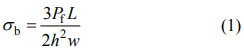
In the formula, h (mm) and w (mm) respectively represent the height and width of the test specimen after cutting and grinding, Pf (N) is the maximum load value when the material is fractured, and L (mm) refers to the span.
2. 4 Characterization of fracture toughness
The creep elastic deformation and plastic deformation tester of Instron5569 was used to measure the fracture toughness. The three-point flexural single-side incision beam method was selected as the test method. The specific steps are: (1) The material is processed into 2 mm × 4 mm × 22 mm size with wire cutting machine, and the notch depth is 2 mm; (2) the angle of the processed sample is polished and chamfered (45°) to eliminate stress concentration; (3) the processed samples were put into the test bench, and were tested at the loading rate of 0.05 mm/min and the experimental parameters of 16 mm span. In order to reduce the experimental error, the average value of 5–8 samples is generally selected as the measurement result. The fracture toughness KIC (MPa·m1/2) of the material is calculated by Eq. (2) [44]:
In the formula, h (mm) and w (mm) respectively represent the height and width of the test specimen after cutting and grinding. P (N) is the maximum load value of the material when fracture occurs, L (mm) is the span, a (mm) is the notch depth of the sample specimen, and Y is the shape factor. In the range of L/h=4, 0 ≤ a/h ≤ 0.6, the specific value can be calculated by Eq. (3) [44]:

2. 5 Characterization of work of fracture
Work of fracture refers to the energy absorbed by a new unit area when a material is subjected to an applied load until it cracks, propagates, and expands in the process of fracture failure. Work of fracture is one of the important indicators to characterize the toughness and damage tolerance of materials. The work of fracture γ can be acquired from Eq. (4) [45]:
In the formula, h (mm) and w (mm) respectively represent the height and width of the test specimen after cutting and grinding, a (mm) is the notch depth of the sample, and W (N·m) is the area enclosed by the load–displacement curve and abscissa in the material test.
2. 6 Characterization of thermal shock property
The thermal shock property was characterized by muffle furnace. The specific steps are as follows: (1) The muffle furnace was connected to the power supply and raised the temperature to the thermal shock test temperature; (2) the flexural strength samples with the size of 3 mm × 4 mm × 36 mm were put into the muffle furnace and held at the test temperature for 15 min to ensure that the temperature of samples was basically the same as the temperature in the muffle furnace; (3) the samples were taken out and put into a water bath at 25 ℃ for cooling; (4) after cooling, the flexural strength of samples was tested and recorded; (5) the critical thermal shock temperature difference of the material was obtained according to ASTM C1525-04 standard [46].
2. 7 Characterization of static oxidation
Muffle furnace was used for static oxidation of material. The specific steps are as follows: (1) The muffle furnace was connected to the power supply and raised the temperature to the static oxidation test value; (2) the static oxidation samples were put into the muffle furnace and held at the test temperature for 15 min to ensure that the temperature of samples was basically the same as the temperature in the muffle furnace; (3) the samples were taken out and put into room temperature to cool after the stated holding time.
2. 8 Characterization of X-ray diffraction analysis (XRD)
The materials were characterized by Empyrean intelligent X-ray diffractive analyzer manufactured by Panalytical Company in the Netherlands. Cu target, Kα (λ = 0.154 nm), was used to characterize the material at a scanning rate of 5 (°)/min under an angular scanning range of 5°−90° at 2θ.
2. 9 Characterization of scanning electron microscopy (SEM) analysis
Scanning electron microscope HELIOS Nanolab600i manufactured by FEI Company of United States was used to characterize the microstructure. This model carries an EDS spectrometer and a backscatter imaging device (BSE) to analyze the elements of material and the ratios between them. The resolution of ion imaging can reach 4 nm under the maximum acceleration voltage of 0.5–30 kV.
3 Results and discussion
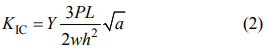
Figure 1 shows the SEM micrographs of individually distributed carbon fibers inside the preform before and after the deposition of PyC interface layer, illustrating different perspectives and magnification times. Figures 1(a) and 1(b) represent the microstructure of randomly selected areas inside the 3D carbon fiber before and after deposition. The uniformity of PyC interface layer is quite good, without apparent carbon nodules or overlaps. This may originate from small molecular chains of propylene and tetrachloromethane used as precursors, which could homogeneously diffuse inside the intra-fascicular and inter-fascicular areas of 3D carbon fibers with fast permeation. A comprehensive comparison of the SEM micrographs from axial and radial directions, as shown in Figs. 1(c)–1(f), indicates that the PyC interface layer with a uniform thickness around 500 nm is successfully deposited along the circumferential direction of individually distributed carbon fibers. Moreover, the structure of carbon fibers before and after the deposition remains intact, without any micro-defects seen from both the axial and radial perspectives. A high-magnification micrograph, Fig. 1(g), reveals the layered crystal structure of the PyC interface. Moreover, there is a gap between the PyC interface layer and fibers, indicating relatively weak interface bonding, which could be beneficial for the fiber pull-out from interface layer. It is of great significance for enriching the fiber pull-out forms and optimizing the fracture toughness compared with composites without a PyC interface layer.
Fig. 1 SEM images of individually distributed carbon fibers inside the preform before and after the deposition of the PyC interface layer, illustrating different perspectives and magnification times: (a) and (b) intrafascicular area; (c) and (d) individually distributed carbon fibers along axial direction; (e) and (f) individually distributed carbon fibers along radial direction; (g) layered crystal structure of PyC interface.
Figure 2 shows the optical images and SEM micrographs of internal microstructure of 3D PyC–Cf/ZrC–SiC composite. The macroscopic large block composite is successfully fabricated, exhibiting no macroscopic defects such as macro-pores or cracks visible to naked eyes. The metallic glossy characteristics of cross-section reflect the dense structure inside the composite. At the same time, the outline of carbon fiber bundles along the z-direction can be clearly captured on the surface, as shown in Fig. 2(a). A further observation of the internal micro-morphology before and after the preparation spanning different magnifications and areas is conducted. Even when the introduction of PyC interface layer reduces the porosity of original 3D carbon fiber, it still could be uniformly filled by a high content of ceramic via vibration assisted ZrC slurry injection and low temperature supplying sintering of SiC without pressure (Figs. 2(b) and 2(c)). As presented in Figs. 2(d) and 2(e), the individual fibers and ceramic phases are evenly and densely distributed no matter inside or between the fiber bundles. After multiple infiltration–curing–pyrolysis cycles, the original morphology of z-direction carbon fibers is well preserved, indicating that the low temperature and pressureless preparation method does not change the structural properties of the z-direction carbon fiber bundle of the braid instead of traditional dozens of impregnation and pyrolysis at temperatures over 1500 ℃ and hot-pressing sintering. In summary, this kind of low-temperature and pressureless preparation approach has a universality, and it can overcome the constraints brought by the size effect and enable the preparation of large-scale macroscopic components.

Fig. 2 Optical images and internal microstructure SEM images of 3D PyC–Cf/ZrC–SiC: (a) large-size macroscopical bulk composites; (b) original carbon fiber preform; (c–e) polished surface spanning various magnifications.
The intra-fascicular microstructure evolution during densification process is shown in Fig. 3. The ZrC powder particles are directly introduced into the interspaces of independently distributed carbon fibers after vibration-assisted slurry injection with considerable content (Fig. 3(a)). Taking a further observation under higher magnification times, the ZrC particles tightly wrap around the fibers, as shown in Fig. 3(d). Afterward, the intra-fascicular microstructures after 4 and 8 cycles of polycarbosilane (PCL) infiltration–curing–pyrolysis are characterized. The SiC ceramic cracked from PCS gradually supplies and fills the intra-fascicular pores left after vibration-assisted slurry injection, which tightly bound the randomly dispersed ZrC particles in the meantime, thereby yielding a dense microscopic morphology as shown in Figs. 3(b) and 3(d)–3(f). Although the cross-section of carbon fiber shows a certain degree of grain coarsening after repeated infiltration and pyrolysis, the overall structure is well preserved under the protection of the PyC interface layer. Figures 3(g)–3(i) show the backscattered-electron (BSE) micrographs of the final composite with different magnifications. The dark and bright phases refer to carbon fibers and ceramics, respectively. The uniform distribution without apparent porosity could be observed in Fig. 3(g). Under higher magnification as shown in Figs. 3(h) and 3(i), the carbon fibers, ZrC, and SiC phases are homogeneously dispersed, and the phase boundary between the fibers and ceramic is distinct. The carbon fiber keeps its roundness well and the structure of PyC interface layer is clearly captured. This kind of dense intra-fascicular microstructure with well protected carbon fiber laid strong foundation for reliable strength and toughness [47].
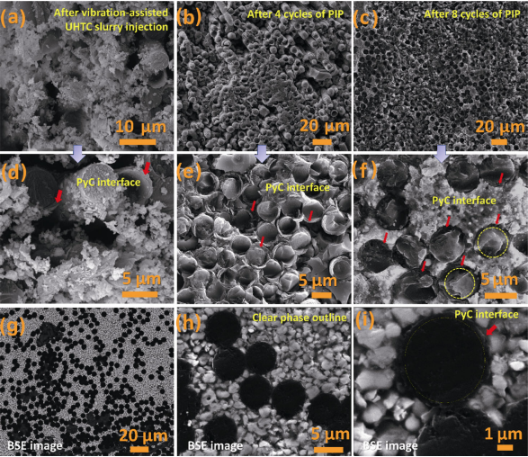
Fig. 3 SEM micrographs of intra-fascicular microstructure evolution during densification process: (a) and (d) after vibration-assisted slurry injection of ZrC; (b) and (e) after 4 cycles of PIP; (c) and (f) after 8 cycles of PIP; (g–i) backscattered-electron (BSE) images for polished surface.
To assess the influence of PyC interface layer on the mechanical properties of the 3D Cf/ZrC–SiC composite, the mechanical behavior is discussed in detail. While the 3D PyC–Cf/ZrC–SiC composite has high flexural strength (251 ± 27 MPa), the fracture toughness is further improved (13.05 ± 1.72 MPa·m1/2). This approach may resolve the difficulty of simultaneous implementation of high flexural strength and fracture toughness in UHTCs. Figure 4 shows stress–strain curves and load–displacement curves of 3D Cf/ZrC–SiC composites with and without PyC interface layer. The stress–strain curves in Fig. 4(a) all present graceful mode for the reason of utilizing 3D carbon fiber as reinforcement. By comparison, there are obvious differences for composites with and without PyC interface layer [39]. First of all, the curve after introducing PyC becomes smoother with slope of linear elastic stage declining, which indicates the decreases in modulus of composite. The modulus mismatch between the carbon fiber and the ZrC–SiC ceramic matrix has always been the noteworthy factor impairing the strengthening and toughening, and the PyC interface layer plays an important role in alleviating the modulus mismatch [48]. Secondly, after introducing the PyC interface layer, the strain corresponding to maximum stress increases from 1.35% to 1.5%–2%, which manifests the improvement of damage tolerance to some degree. Figure 4(b) is a comparison of load–displacement curves of the 3D Cf/ZrC–SiC composite with or without PyC interface layer. Similar to the change of the stress–strain curves, the two composites also experience obvious non-brittle stages. However, after introducing the interface layer, the platform of the nonlinear deformation stage is significantly extended. The displacement corresponding to the maximum load also increases from 0.12 mm to 0.2–0.3 mm. The load decrease is more gradual, showing obvious zigzag characteristics, indicating that the sensitivity of the composite to crack is significantly reduced.

Fig. 4 Stress–strain and load–displacement curves of 3D Cf/ZrC–SiC composites with and without the PyC interface layer: (a) stress–strain curves; (b) load–displacement curves.
To analyze and excavate the mechanism behind the promoted mechanical behavior, the fracture microstructures are characterized using SEM from different angles and magnification times as shown in Fig. 5. The side morphology of tested fracture sample is presented in Fig. 5(a), which demonstrates an “S-shaped” fracture track with considerable fiber pull-outs as shown in the yellow box. In the fracture process, stress concentration will cause interface debonding between the fiber and ceramic matrix. The fiber breaks in the case of extensive strain, and the end of the fiber slips and pulls out from the matrix to absorb energy. Therefore, this kind of “S-shaped” fracture track and fiber bundle pull-out indicate that the material would absorb more energy resulting in a significantly enhanced toughness. When taking a further observation, it is found that the 3D PyC–Cf/ZrC–SiC composite is more arresting in terms of the number and length of fiber pull-outs than the composite without an interface layer. As shown in Figs. 5(b) and 5(c), the fracture surface appears as fascicular fiber pulled-out with thousands of individual fibers. Moreover, the length of pulled-out carbon fibers is more than 500 µm. This excellent fiber pull-out performance originates from the low temperature preparation without pressure and the introduction of PyC interface layer. The carbon fibers are effectively protected no matter from the perspective of macroscopical 3D structure or individual distributed one (as shown in Figs. 5(d) and 5(e)), which ensure their original excellent mechanical performances. In addition, the PyC interface layer also builds up dual weak interfaces of fiber–ceramic matrix and fiber–PyC (as the red arrow pointed in Fig. 5(e)), effectively alleviating the mismatch in the thermal expansion coefficient and modulus. Thereby, the energy consumption during the fracture process is significantly increased by fiber debonding and slippage. The fibers can be solely pulled out from the PyC interface layer or from ceramic matrix together with the interface layer. This kind of multiple forms of fiber pull-out enables the material to absorb more energy, resisting and consuming the external force loading process, thereby enhancing the damage resistance and fracture toughness.
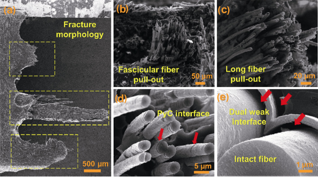
Fig. 5 SEM micrographs of the microstructure of fracture surface: (a) side surface; (b) fascicular fiber pull-out; (c) long fiber pull-out; (d) PyC interface; (e) dual weak interface.
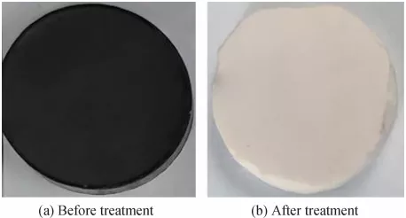
Thermal protection material often encounters rapid heating and cooling during the preparation and service life. Rapid changes in ambient temperature generate transient thermal stress that usually strongly influences the material’s surface, posing a severe risk to structural safety. Therefore, the thermal shock resistance is an important indicator of judging the reliability of thermal protection material. In this work, water quenching was used to characterize the thermal shock resistance of 3D PyC–Cf/ZrC–SiC composite from room temperature (RT) to 1200 ℃, and the critical temperature difference of thermal shock was calculated. Figure 6(a) shows the macroscopic photographs of the 3D PyC–Cf/ZrC–SiC composite before and after thermal shock at different temperatures. None of the test specimens exhibit visible surface penetration cracks, peeling, or structural cracking. The sample surface appears slightly white when the temperature exceeds 800 ℃, which could originate from oxidation of ZrC ceramic under low temperature (the oxidation starts at 800 ℃). On the whole, the 3D PyC–Cf/ZrC–SiC composite can withstand the instantaneous thermal stress generated by thermal shock at wide temperature range spanning from RT to 1200 ℃. In comparison, traditional UHTCs are prone to structural damage after the thermal shock at 200–400 ℃. This confirms the excellent thermal shock resistance of 3D PyC–Cf/ZrC–SiC composite.
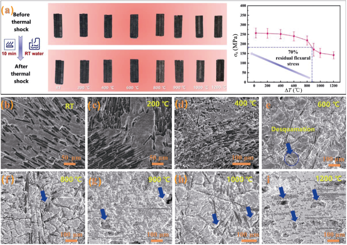
Fig. 6 Thermal shock resistance of 3D PyC–Cf/ZrC–SiC composite and SEM micrographs of the sample surface after thermal shock: (a) photographs of composite before and after the thermal shock at different temperatures from RT to 1200 ℃, residual strength (σR) as a function of thermal shock temperature difference (ΔT) of the composite after the thermal shock; (b) RT; (c) 200 ℃; (d) 400 ℃; (e) 600 ℃; (f) 800 ℃; (g) 900 ℃; (h) 1000 ℃; (i) 1200 ℃.
The flexural strength of samples after the thermal shock was measured to quantitatively evaluate the thermal shock resistance. The critical temperature difference of thermal shock was calculated, and the relationship curve between the residual flexural strength and thermal shock temperature difference was obtained (Fig. 6(a)). The residual flexural strength remains relatively stable in the temperature range from RT to 400 ℃. When the thermal shock temperature difference exceeds 400 ℃, the residual flexural strength slowly declines, which decreases faster when the temperature exceeds 800 ℃. This could be due to the initial oxidation of ZrC ceramic at 800 ℃, lowering the flexural strength to some degree. The calculated critical temperature difference of thermal shock of 3D PyC–Cf/ZrC–SiC composite is 875 ℃, which is nearly 3 times higher than that of traditional UHTC materials, displaying excellent thermal shock resistance. Normally, the strong covalent bonds, low grain boundary, and bulk diffusion rates result in poor thermal shock resistance upon rapid temperature changes. Especially when UHTC is rapidly cooled, the surface undergoes apparent tensile stress, which is more likely to destroy UHTC compared with compressive stress [49]. Figures 6(b)–6(f) show the surface microstructures of 3D PyC–Cf/ZrC–SiC composite sample after thermal shock at different temperatures. It is observed that there are almost no surface cracks or peeling of the samples at temperatures from RT to 400 ℃ (Figs. 6(b)–6(d)). The fine pores on the samples’ surface as shown in Figs. 6(e) and 6(f) are favorable for alleviating the thermal stress during the thermal shock process to some extent and improving the thermal shock resistance as a result. It should be noticed that structure of the carbon fiber remains intact after the thermal shocks at different temperatures without oxidation or peeling. This shows that the structural damage of carbon fiber is suppressed under the protection of PyC interface layer, which also explains the reason of improved thermal shock resistance.
Besides the mechanical properties and thermal shock resistance, static oxidation is another important index to analyze and evaluate the physical and chemical stability of UHTC. Figure 7 shows the morphologies and components of 3D PyC–Cf/ZrC–SiC composite after static oxidation at 1500 ℃ for 30 min. Before the static oxidation, the surface of the 3D PyC–Cf/ZrC–SiC composite block exhibits glossy metallic reflectance (the macroscopic photograph in the upper right corner of Fig. 7(a)). The microstructural and corresponding EDS results show that after repeated infiltration and pyrolysis of the SiC ceramic precursor, the main components on the surface are ZrC, SiC, and C (carbon fibers). After the static oxidation at 1500 ℃ for 30 min, the surface shows grayish-white features, as shown in the macroscopic photograph in the upper right corner of Fig. 7(b). And the microstructure of corresponding area appears roughly glassy with EDS analysis of Zr, Si, and O. The XRD result in Fig. 7(c) indicates the presence of ZrO2 and SiO2 phases on the surface. Therefore, it can be inferred that the oxide layer after the static oxidation at 1500 ℃ for 30 min is mainly composed of ZrO2 and SiO2 phases, which is formed by the oxidation of ZrC and SiC. Although the 3D PyC–Cf/ZrC–SiC composite can form a relatively dense oxide layer in most areas after the static oxidation, the oxide layer formed on the local surface is relatively thin with ceramic particles covered by the oxide layer as shown in Fig. 7(d). Besides, there are a few bubbles on the surface (indicated by the red arrow in Fig. 7(d)), which may be caused by the volatilization of ZrO2 from the oxide layer.
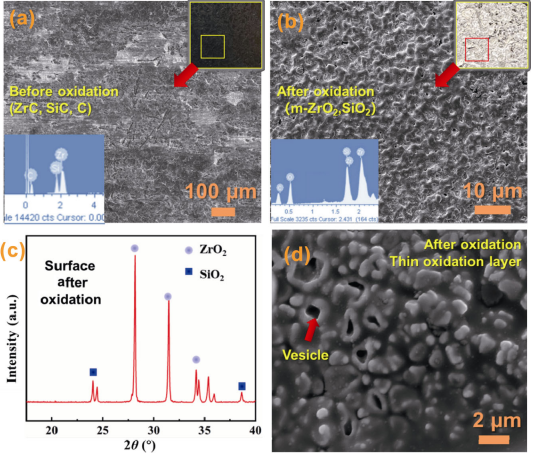
Fig. 7 Macrostructural and microstructural characteristics of the surface of 3D PyC–Cf/ZrC–SiCcomposites before and after oxidation at 1500 ℃ for 30 min with EDS and XRD analyses: (a) before oxidation; (b) after oxidation; (c) XRD of surface after oxidation; (d) thin SiO2 layer and EDS analysis.
To understand the static oxidation behavior of the 3D PyC–Cf/ZrC–SiC composite, the microstructural characterization and analysis of the profile after static oxidation were performed. Figure 8 shows the microstructural profile of 3D PyC–Cf/ZrC–SiC composite after static oxidation at 1500 ℃ for 30 min, demonstrating the overall morphology of oxide layer and composite matrix. Figure 8(a) indicates that the oxide layer of the 3D PyC–Cf/ZrC–SiC composite mainly consists of a bilayer structure. The outer layer is about 150 µm, which consists of ZrO2 and SiO2, exhibiting relatively dense microstructure as presented in Fig. 8(b). This kind of dense oxide layer has reliable physical and chemical stability and resists the erosion from fierce oxidizing atmosphere, ensuring the excellent oxidation resistance of the composites. Combined with the EDS analysis results (the ratio of atomic numbers), it could be concluded that the inner layer is composed of ZrO2, with a thickness of about 170 µm. It appears as a particle stacking structure, with some holes in Fig. 8(c). Below the oxide layer is the 3D PyC–Cf/ZrC–SiC composite matrix. The oxide layer protects the matrix, and the presence of the z-direction carbon fiber structure can be clearly observed in Fig. 8(a).
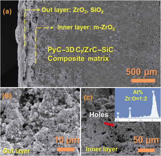
Fig. 8 SEM micrographs of the oxide layer of PyC–3D Cf/ZrC–SiC composite after the oxidation at 1500 ℃ for 30 min: (a) overall profile; (b) random out layer area; (c) random inner layer area.
During the static oxidation process, ZrC and SiC are first oxidized to produce ZrO2 and SiO2 due to the sufficient oxygen partial pressure. As oxygen atoms gradually diffuse into the interior of composite, the inner layer starts to oxidize. The carbon fibers oxidize to CO and CO2 gases, SiC yields SiO2, while ZrC forms ZrO2. The rapid oxidation and depletion of carbon fibers and SiC in the inner layer result in stacking particle morphology. Figure 8(b) shows the holes that remained after the fiber oxidation. With the prolonged oxidation, the liquid phase SiO2 content of surface gradually increases. The liquid SiO2 phase promotes the ZrO2 sintering and partly fills the pores formed by the ZrO2 volatilization, so that the protective ability of the outer oxide layer is gradually enhanced, forming a relatively dense structure [50]. Figure 9 shows the micro-morphology of carbon fiber in the transition region between the oxide layer of the 3D PyC–Cf/ZrC–SiC composite and the matrix after the static oxidation. Although the carbon fiber is oxidized to a certain extent, the fiber’s structure is well preserved by the sacrifice and protection of PyC interface layer, exhibiting no traces of severe corrosion. This shows that the PyC interface layer provides protection to the carbon fiber during the static oxidation experiment at 1500 ℃ for 30 min.
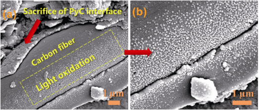
Fig. 9 Microstructures of the carbon fiber on the 3D PyC–Cf/ZrC–SiC composite surface after the static oxidation at 1500 ℃ for 30 min: (a) low magnification times; (b) high magnification times
4 Conclusions
In this study, PyC modified 3D carbon fiber was utilized to reinforce UHTC. The macroscopic bulk composite is successfully fabricated through low temperature sintering at 1300 ℃ without pressure. The PyC interface layer not only constructed protective barrier for carbon fiber, but also introduced weak interface layer between individual fiber and ceramic matrix. As a result, it effectively alleviated the mismatch of thermal expansion coefficient and modulus between fiber and ceramic matrix, and stimulated toughening mechanisms, such as interface debonding, crack deflection, crack bridging, and fiber pull-out. The low temperature sintering at 1300 ℃ without pressure could overcome the constraints brought by the size effect and enable the fabrication of large-scale bulk components. Moreover, it has great universality to achieve the uniform introduction, stacking, and sintering of high content of UHTCs with arbitrary components and particle sizes inside 3D carbon fibers at low temperature without pressure. Under the synergistic effect of PyC interface layer and low temperature sintering without pressure, the prepared 3D PyC Cf/ZrC–SiC composites simultaneously possesses reliable fracture toughness at 13.05 ± 1.72 MPa·m1/2 and flexural strength at 251 ± 27 MPa. After rapid thermal shock spanning from RT to 1200 ℃, there are no visible surface penetrating cracks, spalling or structural fragmentation. The maximum critical temperature difference reaches 875 ℃, which is nearly three times higher than that of traditional monolithic ceramics. The haunting puzzle of intrinsic brittleness and low damage tolerance are resolved fundamentally. The carbon fibers around oxide layer and matrix remains structure intact after static oxidation at 1500 ℃ for 30 min. The oxide layer has reliable physical and chemical stability and resists the erosion from fierce oxidizing atmosphere, ensuring the excellent oxidation resistance of the composites. This work not only breaks the size constraints, but also strikes a balance between strength and toughness as well as take account of stable thermal shock resistance and oxidation resistance, which realizes strengthening-toughening and oxidation resistance synergy in the true sense. This work provides a strong theoretical and technical support for the engineering applications of 3D carbon fiber toughened UHTC composites.
References: omitted
Declaration: This article is provided by CERADIR™ users or obtained from Internet, the content does not represent the position of CERADIR™. We are not responsible for the authenticity/accuracy of the article, especially the effects of the products concerned. This article is for study only, it does not constitute any investment or application advice. For reprinting, please contact the original author. If it involves the copyright and/or other issues, please contact us and we will deal with it asap! CERADIR™ has the interpretation of this declaration.