Abstract
Manufacturing and testing electric propulsion systems can be very expensive both in economic and time terms. One of the main limiting factors is the manufacturing of ceramic components, such as alumina. However, the advent of 3D printing has made it possible to produce complex-shaped components made of technical ceramics at low cost and in reduced time. This paper illustrates the advancements made by the University of Pisa in Fused Filament Fabrication of alumina components for electric propulsion purposes. Rapid prototyping can help not only in manufacturing thrusters in a faster and cheaper way but also in producing more complex geometries, resulting in more efficient thrusters. The alumina produced through this method has achieved near-full density and a flexural strength of 430 MPa. Components manufactured with this technique successfully passed vibration and pyroshock tests. This manufacturing approach was already used in the framework of the CHEOPS-VHP-BB (Consortium for Hall Effect Orbital Propulsive System-Very High Power-Building Blocks) project to produce the insulating components of a high-current hollow cathode.
Keywords: Electric propulsion, Hall thrusters, Hollow cathode, Additive manufacturing, Fused filament fabrication, Alumina
Introduction
Technical ceramics play a critical role in the development of electric propulsion systems for spacecraft thanks to their peculiar thermal, mechanical, and electrical properties. In fact, the integration of technical ceramics into electric propulsion systems, such as Hall Thrusters (HTs) and gridded ion thrusters, is essential for several components that serve as electric insulators or that are directly exposed to the plasma. As space missions push the boundaries of technology, the demand for reliable and high-performance materials has led to the increasing adoption of technical ceramics in the construction of thrusters and cathodes.
Among the various types of ceramics, alumina (Al2O3) stands out due to its high melting point, excellent insulation capabilities, chemical inertness, and remarkable resistance to wear and corrosion, making it ideal to withstand the extreme conditions these components are exposed to without degrading [1, 2] Nevertheless, due to its high hardness, alumina's machinability is limited, often requiring diamond-coated tools or other expensive and time-consuming processes. Additionally, its brittleness can lead to chipping or cracking during machining. To address these issues, alumina components are typically produced by shaping powders mixed with additives. These additives are then removed, and the shaped components are sintered in a kiln. Common methods for shaping include ceramic injection molding, dry pressing, isostatic pressing, slip casting, and extrusion. However, these traditional techniques are often costly, unsuitable for small production runs, or not adaptable to producing complex shapes [3].
The advent of additive manufacturing (AM) has revolutionized the production of technical ceramics. AM encompasses a variety of innovative processes that build parts layer by layer, which significantly reduces labor costs and material waste while enabling the production of intricate and complex geometries. Although AM is less suited for high-volume production and can present challenges such as internal porosity, high surface roughness, and anisotropy, it has proven to be highly effective for creating alumina components.
Powder-based AM technologies, such as selective laser sintering (SLS) [4], stereolithography (SLA) [5], and digital light processing (DLP) [6] have already demonstrated promising results with alumina. In recent years, material extrusion additive manufacturing (MEAM) has gained widespread adoption due to its inherent simplicity, versatility, and reduced costs. Originally developed for producing components from thermoplastic polymers, MEAM has been adapted to create both metal and ceramic parts [7]. This process involves heating and extruding material through a nozzle to construct a 3D structure layer by layer. The most common form of this technology, known as Fused Filament Fabrication (FFF) or Fused Deposition Modeling (FDM), uses a filament composed of a polymer binder mixed with ceramic powder. The resulting printed object, referred to as the green part, undergoes a debinding phase to remove the polymer binder. This debinding can be done chemically with a solvent or catalytically in an acid atmosphere. After debinding, the component, now called the brown part, undergoes a thermal cycle in a furnace. This thermal cycle has two phases: thermal debinding, which removes the remaining binder (backbone), and sintering, where the powders are heated to just below the material's melting point, causing the particles to fuse together and form a dense, cohesive structure. The final product, known as the white part, is a fully dense alumina component. This layered approach not only allows for the creation of complex geometries but also offers a faster and more cost-effective alternative to traditional manufacturing methods, making it an attractive option for producing advanced ceramic components for various applications, including space propulsion systems.
Additive manufacturing is gaining interest for the production of ceramic components in industry, but its use in space applications remains largely unexplored. To the best of the authors' knowledge, the only documented application of FFF for ceramic components in a space-related context is presented by Sieder-Katzmann et al. [8], who demonstrated the fabrication of a ceramic aerospike cold gas demonstrator. However, no prior studies have investigated the feasibility of using FFF to produce alumina components specifically for Hall thrusters or other electric propulsion systems. This work aims to address this gap by assessing the suitability of FFF for manufacturing ceramic components for electric propulsion and evaluating their material properties.
This paper is divided into the following sections. Section "Manufacturing of Alumina Components" describes how FFF manufacturing process can be adopted to produce alumina components. In particular, it focuses on the material characterization and the various stages that are necessary to obtain a component, i.e., printing, debinding and sintering. Section "Sintered Alumina Characterization" of the paper describes the density and dimensional analysis of sintered alumina, together with its mechanical properties. Section "Alumina Components for Hall Thrusters" showcases some applications of this technology, and, in particular, it focuses on an insulating plate for a HT hollow cathode for high-power applications in the ambit of the Consortium for Hall Effect Orbital Propulsive System-Very High Power-Building Blocks (CHEOPS-VHP-BB), a Horizon Europe Project which aims to advance the study of high-power HTs. This section discusses how the implementation of such a technology can affect the design process of the cathode, thus allowing a more efficient design, and the results of mechanical tests on the component are shown. Finally, Section "Conclusions" sums up the main findings of this study.
Manufacturing of alumina components
Material extrusion offers several advantages over other additive manufacturing technologies. It is notably cost-effective, particularly in comparison to powder-bed fusion, and does not present safety concerns associated with powders and resins. Moreover, FFF printers are generally user-friendly and straightforward to operate, requiring minimal training for setup and operation. Furthermore, this technology allows for easier material changes within the same machine, enhancing its versatility. However, parts produced via FFF often exhibit noticeable porosity, which can compromise their mechanical properties [9]. Additionally, the inherent anisotropy of the printing process can result in varied mechanical properties along the build direction, although this effect, including its impact on porosity, tends to diminish during the sintering phase [10]. Nonetheless, meticulous optimization of printing parameters can effectively mitigate porosity issues.
After a brief overview of the feedstock characterization, this section illustrates in detail the printing process, and debinding and sintering phases involved in FFF of alumina.
Feedstock characterization
The feedstock used in this study is a 1.75 mm diameter alumina filament manufactured by Zetamix (Nanoe, Ballainvilliers, France), specifically designed for FFF technology. According to the producer's specifications, the filament consists of 17 wt% (corresponding to 48 vol%) of a polyolefin-based binder system, with the remaining 83 wt% (52 vol%) being alumina powder, characterized by particle sizes smaller than 1 μm.
To understand the thermal decomposition behavior of the binder system, a 5.43 mg sample of the filament underwent thermogravimetric analysis (TGA) up to 700 °C. The TGA results, depicted in Fig. 1, reveal several distinct mass loss signals corresponding to different organic compounds. Initially, a slight weight loss of approximately 0.3% below 100 °C suggests the removal of surface-adsorbed water. Subsequently, significant mass losses occur at higher temperatures: the first major signal at 230 °C corresponds to a weight loss of 5.4%, followed by a second signal at 331 °C with an additional mass loss of 15.9%, and a third signal at 461 °C with a loss of 2.5%. The residue remaining after thermal debinding at 510 °C is 76.3%, which deviates from the theoretical residue of 82% provided by the producer.
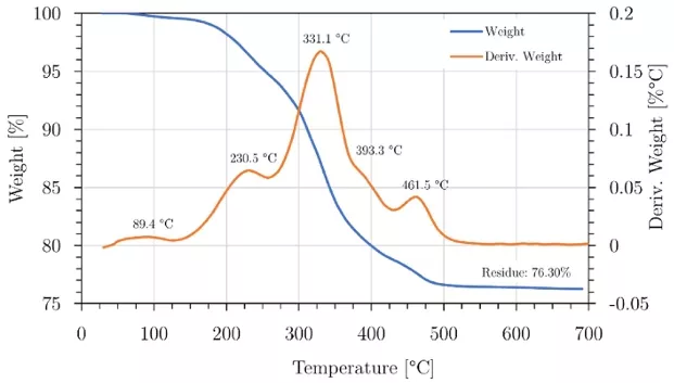
Fig. 1 Results of the TGA of a sample of alumina filament
Printing phase
The components are fabricated using a Mingda Magician X, a low-cost 3D printer, equipped with a direct drive extruder. The nozzle was changed with a 0.6 mm hardened steel nozzle, to prevent any wear and therefore inconsistent flow. Other modifications include replacing the filament adjustment screw and spring with a nut and screw to reduce filament stress, which tends to break at lower external temperatures, and the addition of a flexible magnetic steel sheet with a PEI coating in order to facilitate the component removal from the plate after printing. To enable filament extrusion, which requires relatively lower temperatures compared to other filaments, the printer's firmware was modified to disable the minimum operating temperature. In fact, it was found that 120 °C is the optimal printing temperature, as lower temperatures can result in clogging the printer, and higher temperatures can cause sagging on the printed components [11].
Although the filament producer suggests a 130% oversizing factor in the Z direction and 126% in the X–Y directions, the components are scaled up by 130% in all dimensions based on the measurements of previous tests.
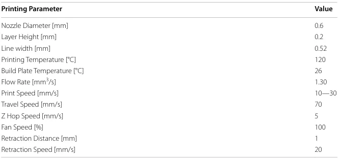
The layer height was chosen to be 0.2 mm, a classical choice for a 0.6 mm nozzle, even if lower layer heights can be selected for higher accuracy. A 0.52 mm line width was chosen because printing lines slightly smaller than nozzle tend to improve the strength of the printed object since in this way the nozzle can fuse adjacent rasters together when it makes a second pass to some extent over the previous one. An extrusion flow rate of 1.30 mm3/s was found to result in a higher density of sintered alumina, without any backlash on shape retention [11]. Printing speed can be set in a span ranging from 10 mm/s, to maximize accuracy, up to 30 mm/s, preferable for larger parts. Retraction settings included a 1 mm distance and 20 mm/s speed to prevent stringing. The build plate remained unheated as adhesion and cooling-induced shrinking were not issues, while maximum fan speed was utilized for effective cooling during printing. A summary of all printing parameters is provided in Table 1.
Table 1 Summary of printing parameters
Debinding and sintering
The debinding process takes place in two distinct stages: chemical debinding, which utilizes a solvent to dissolve the main binder, and thermal debinding, in which the remaining polymer, i.e., the backbone, degrades. This latter phase takes place in a furnace immediately preceding the sintering process.
Chemical debinding is carried out by immersing the components in a beaker, or larger container, containing 20 ml of pure acetone for each gram of the green part, maintaining them in the same orientation as printed. A temperature-controlled ultrasonic bath is employed to keep the samples and solvent at 40 °C for 8 h without activating the ultrasonic function. Subsequently, the components are removed from the solvent and allowed to air-dry for at least 2 h. Nevertheless, larger components can require longer debinding and drying times.
The thermal cycle consists of two phases: thermal debinding, which removes the residual polymer, and sintering, which promotes particle coalescence to form a dense part. This process is conducted in a Zetasinter tubular furnace under ambient air conditions, as controlled atmosphere is typically unnecessary for ceramics. The specific parameters of the cycle adhere to the manufacturer's recommendations (refer to Fig. 2). Sintering occurs at 1550 °C, employing solid-state sintering since the melting point of alumina exceeds 2000 °C [12]. The entire cycle spans approximately 53 h.
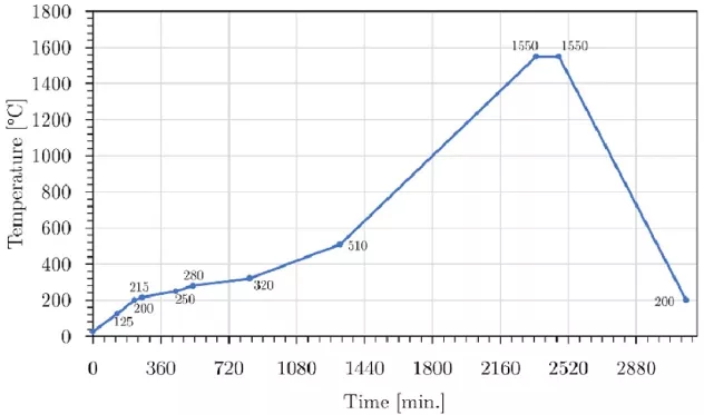
Fig. 2 Thermal debinding and sintering cycle of alumina components
Sintered alumina characterization
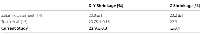
To comprehensively investigate the properties of sintered alumina, 45 specimens were fabricated for experimental analysis. These specimens were specifically prepared for 3-point bending tests following the guidelines outlined in ISO 14704:2016 [13], necessitating dimensions of 4 × 3 × 36 mm3. To account for expected shrinkage during the sintering process, the printed parts were scaled up to dimensions of 5.2 × 3.9 × 46.8 mm3 (Fig. 3).
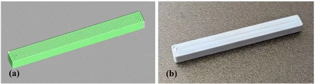
Fig. 3 A preview of the printing path of a sample on UltiMaker Cura (a), and a picture of a printed sample (b)
Prior to testing, the specimens underwent rigorous dimensional analysis and measurement to assess accuracy and consistency. Additionally, density measurements were conducted using the buoyancy method, involving precise weighing in demineralized water. Subsequently, the specimens were subjected to 3-point bending tests to evaluate their flexural strength, a critical mechanical property essential for assessing the structural integrity of ceramic materials.
Mass loss and geometry analysis
Throughout the manufacturing process, the specimens were regularly weighed to assess mass changes. Chemical debinding resulted in a mass loss of 16.0 ± 0.2%, whereas during the thermal cycle, which encompasses thermal debinding and sintering, the samples exhibited an additional mass reduction of 8.1 ± 0.1%. This mass loss aligns closely with the residue observed in the TGA analysis, suggesting a lower alumina content in the filament than what was initially specified by the supplier.
From a dimensional perspective, the components perfectly maintained their shape. The shrinkage s measured approximately 23% in all directions, effectively compensating for the 130% oversizing factor OSF implemented during the printing process, as confirmed by preliminary tests. This shrinkage was accounted for by applying the straightforward relationship:

Although the values in the X–Y directions deviated from those provided by the filament producer [14] and from those reported by Tosto et al. [15]. using the same filament, as illustrated in Table 2. This disparity highlights the influence of the manufacturing process on shrinkage characteristics and underscores the potential to mitigate the inherent anisotropy of the 3D printing process.
Density
All 45 specimens underwent density measurements using the buoyancy method. Sintered samples were meticulously weighed in air and demineralized water. Each weighing was performed three times, and the average value was used for analysis. These values were then used to determine the density based on Archimedes’ principle, following ASTM D792-20 guidelines [16]:

Here, ρ represents the density of alumina, ρair is the density of air, ρwater is the density of water, wair is the weight of the alumina sample in air, and wwater is the weight of the alumina sample in water. The calculated densities ranged from 3.80 ± 0.02 g/cm3, corresponding to relative densities between 94.8% and 99.9% when assuming a reference density for alumina of 3.99 g/cm3.
A comparison with existing research on FFF of alumina shows that similar density values have been reported. For the same filament, the very same relative density range was reported by Tosto et al. [15], while the values from Truxová et al. [17] also fall within this range, confirming the consistency of FFF-processed alumina densities with previous studies.
It is worth noting that for electric propulsion applications, there are no specific density guidelines for ceramic components, provided their mechanical and thermal properties remain adequate. Generally, relative densities above 96% are accepted in most aerospace applications, although more porous alumina components may be required for certain
specific applications [18].
Table 2 Shrinkage of parts printed with Zetamix alumina filament
Flexural strength
The mechanical properties of sintered alumina were evaluated by testing the specimens using 3-point bending tests following ISO 14704:2016 guidelines [13].
Testing was conducted on a Schenck universal testing machine with a 2 kN loading cell, employing a crosshead displacement rate of 0.5 mm/min and a sampling frequency of 20 Hz. The test setup is shown in Fig. 4. The specimens exhibited brittle fracture near the center, characterized by predominantly transverse fracture surfaces indicative of good interlayer adhesion. The flexural strength σf was calculated using the formula:

Here, F is the fracture load, a is the length of the fixture moment arm, b is the specimen width, and d is the specimen thickness, parallel to the direction of the test force.
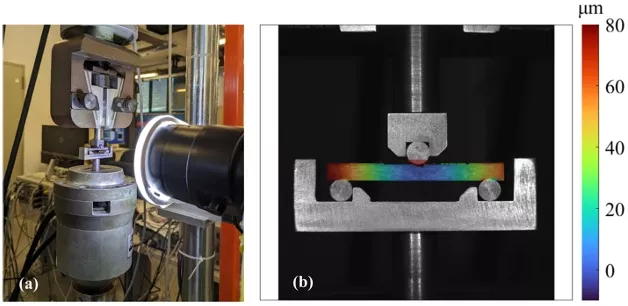
Fig. 4 The 3-point bending test set up (a) and digital image correlation (DIC) close view (b)
The specimens yielded a value of 331.5 ± 101.5 MPa, where the large scattering in the flexural strength is due to the brittle behavior of alumina. These results are at least slightly higher than those obtained by similar studies [15, 17]. For reference, commercially available alumina ceramics typically exhibit flexural strengths ranging from 250 to 400 MPa, with higher purity versions reaching up to 600 MPa [19], even though these properties are significantly influenced by the specific manufacturing processes employed and can vary meaningfully from sample to sample [20].
Alumina components for Hall thrusters
The production of alumina components through FFF has already been employed multiple times at the University of Pisa in various activities related to electric propulsion, despite being a technology still in development. This is not surprising, considering the enormous advantages it offers, not only in terms of design but also logistically. Indeed, while FFF allows for the creation of particularly complex geometries or lighter components thanks to less than 100% infill, its greatest advantage lies in the ability to produce effective components in just a few days and at minimal costs.
For instance, this technology has been utilized to produce a support spool for the heater of a hollow cathode (Fig. 5a) [21] and components for the feed system of an iodine cathode (Fig. 5b). It has also been used to manufacture a discharge channel for a low-power HT (Fig. 5c), as alumina serves as an excellent, cost-effective alternative to boron nitride [22].
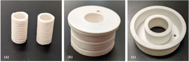
Fig. 5 Different alumina components obtained through FFF: two spools for a heater (a), a tap for an iodine feeding system (as printed) (b), and a low-power HT discharge channel
In addition, the use of FFF for alumina components is being explored to manufacture ceramic parts of a new version of a high-current hollow cathode in the framework of CHEOPS-VHP-BB project (Consortium for Hall Effect Orbital Propulsive System-Very High Power-Building Blocks), a Horizon Europe initiative in which the University of Pisa and Aerospazio Tecnologie S.r.l. are involved, which is aimed to enhancing high-power HT capabilities for deep space missions. The hollow cathode designed for CHEOPS (Fig. 6) is an advanced version of the cathode for TANDEM, a dual-channel magnetically shielded HT developed by the University of Pisa and Aerospazio Tecnologie S.r.l. [23]. This new version is optimized for a wide range of propellants, reduced weight, and robust configuration to endure environmental tests such as mechanical shock and vibration.
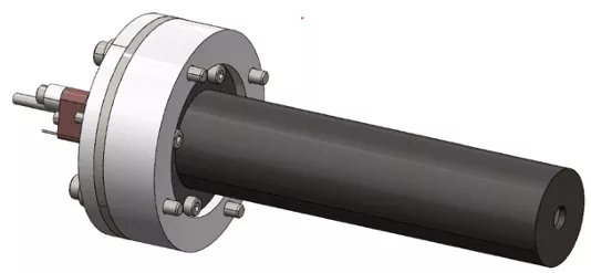
Fig. 6 View of the CAD of the CHEOPS hollow cathode
The application of FFF in this context allows for the rapid and cost-effective production of ceramic components, which are critical for the cathode’s performance and longevity. By leveraging FFF, the project aims to achieve more compact and efficient designs, ultimately contributing to the development of more mature and reliable propulsion systems. In this sense, this section showcases the production of an insulating plate for the hollow cathode and its preliminary acceptance tests.
Insulating plate for a high-current hollow cathode
The component’s primary role is to electrically insulate the cathode tube from the main flange while withstanding all operational loads throughout the cathode’s lifespan. This includes all the intense mechanical stresses experienced during launch on a rocket.
Due to its relatively large size (outer diameter of approximately 65 mm), the component was printed at a speed of 30 mm/s. Additionally, a 20% gyroid infill pattern was used. This choice offers several advantages: it reduces printing time, facilitates the debinding process by minimizing the risk of deformations caused by incomplete binder removal, and significantly decreases the overall weight of the component. In total, the printing process took approximately 7 h. The component is shown in Fig. 7a.
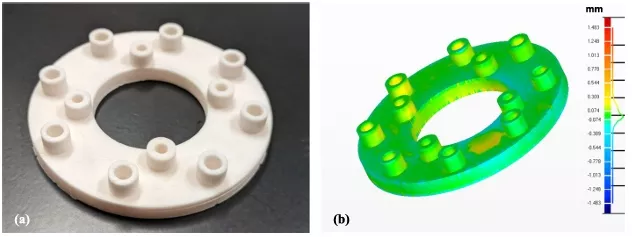
Fig. 7 A picture of the sintered alumina plate for the CHEOPS hollow cathode (a), and a comparison between the actual dimensions and the CAD dimensions (b)
To confirm compliance with the dimensional requirements, the component underwent an optical scan. Specifically, a 3Shape E2 scanner was used for this purpose. This scanner projects a light source onto the area to be scanned and captures thousands of images with imaging sensors. The images are processed by the scanning software, which then produces an accurate 3D surface model. This model can then be compared with the original CAD design to evaluate, point by point, whether the manufactured component meets the requirements. This comparison (shown in Fig. 7b) shows that the shrinkage was almost perfectly compensated, with a mean deviation in the order of 0.1 mm. No significant defects were detected.
The total estimated cost of producing the insulating plate, including material, energy, and consumables, was calculated. Specifically, the cost breakdown includes €45 for feedstock material, €70 for energy consumption during the thermal cycle (assuming an electricity price of €0.25/kWh), and €25 for the debinding solvent, resulting in a total cost of approximately €140 per part. Notably, this cost estimation applies to a single component. If multiple components are processed simultaneously within the same furnace cycle, the per-unit cost would decrease accordingly.
While direct comparisons with other manufacturing techniques, such as slip casting or injection molding, are complex due to variations in geometry and batch size, it is worth noting that for custom or small-series components with complex geometries, production costs using traditional methods can easily exceed €1,000 per piece.
While conventional manufacturing typically incurs substantial costs for direct labor and machine operation, FFF offers a key advantage due to its relatively low equipment cost, around €15,000. This makes FFF a more accessible option for research and prototyping, especially compared to high-end industrial equipment, which generally requires a significantly higher capital investment. Additionally, unlike processes such as injection molding, FFF does not require costly molds, which significantly increase production costs for small batches. For smaller components, the energy cost can also be further optimized by processing multiple parts simultaneously in a single furnace cycle. A more detailed discussion on the cost comparison between FFF and other ceramic manufacturing methods can be found in the work of Nötzel et al. [24].
The cathode was designed to withstand random vibration and pyroshock loads related to an eventual launch, ensuring its reliability and durability in operational conditions. To validate the resistance of components manufactured by FFF, the alumina plate, considered one of the most critical parts, was subjected to random vibration and pyroshock tests. It is worth noting that, in the absence of the complete thruster assembly, the loads were applied directly to the base of the cathode during this initial design phase. As a result, the test outcomes are highly conservative, as they do not account for the damping effects that would arise from the coupling between the cathode and the thruster.
For the random vibration environment, the alumina piece was mounted alongside a dummy cathode made of aluminum to simulate the operational conditions accurately. The dummy was engineered to have the same mass and principal moments of inertia as the real cathode, providing a precise representation of the dynamic behavior during testing. The subassembly was tested on a TIRA GmbH TV 5500 shaker, located at the DICI-UniPi laboratories, as shown in Fig. 8. The random accelerations used for the test are summarized in Table 3. After the test, no damage was observed on the component.
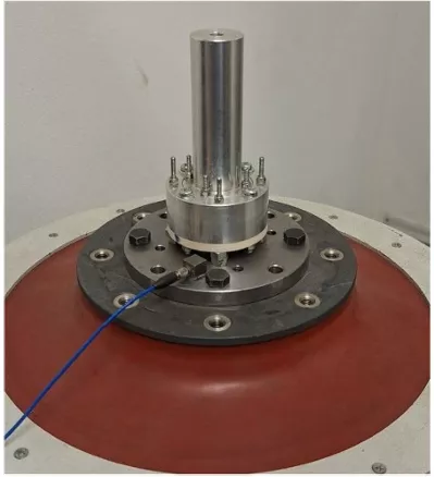
Fig. 8 The alumina flange assembled with the dummy cathode on the shaker before the random vibration test
Table 3 Random accelerations
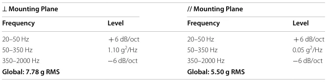
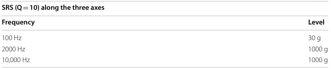
Pyroshock tests are typically performed on components such as electronics, mechanisms, valves and brittle materials that could suffer from major failures due to the vibration induced by pyrotechnical devices. The shock environment consists of a transient mechanical loading with short duration and high amplitudes. Due to its inherently stochastic nature, it is difficult to describe the shock environment in terms of a signal time history. Therefore, shocks are usually described in terms of their Shock Response Spectrum (SRS). The SRS is a calculated function based on an input transient. It allows characterizing the shock effect on a dynamical standardized system to estimate its severity or its damaging potential. Thus, it allows shocks to be compared with each other or an equivalence criterion to be established between a measured transient environment and a laboratory simulation of that transient environment [25]. The alumina piece mounted on the dummy cathode was tested to the SRS shown in Table 4.
Table 4 Shock Response Spectrum
The assembly was tested in an external laboratory, following the MIL-STD-810H-2019 [26] standard for environmental test methods. The setup consisted of a vibrating steel plate (or a cantilever attached to the plate during the testing phase for axes orthogonal to the cathode axis) on which the cathode was mounted. The plate was set into vibration by the impact of a projectile fired from a compressed-air cannon, striking the face of the plate opposite to the specimen, see Fig. 9. Being an open-loop test where the operator must manually modify the test parameters to comply to the required SRS, a calibration dummy made entirely in aluminum with the same inertial properties of the cathode was used during the calibration phase. This precaution was necessary since the maximum acceleration during calibration could exceed the required value by a factor of ten, potentially compromising the alumina component before the actual test.
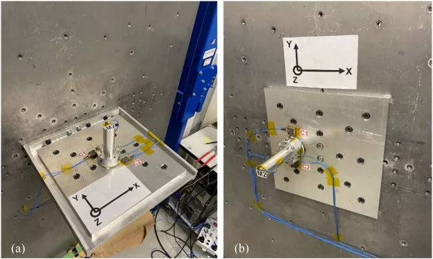
Fig. 9 The alumina flange assembled with the dummy cathode mounted on the cantilever for x-axis and y-axis shock tests (a) and directly on the steel plate for z-axis shock test (b)
Three shocks per axis were reproduced in accordance with the qualification standard. Following the test for each axis, the component was disassembled, and the alumina part underwent visual inspection. At the end of the tests, the printed alumina piece was found intact, confirming that FFF is an effective method to produce components capable of withstanding the environmental loads typical of space applications.
Conclusions
This article highlights significant advancements in the production of alumina components for electric propulsion systems using FFF technology. It has been demonstrated that adopting FFF provides a cost-effective and time-efficient alternative to traditional manufacturing methods. The comprehensive characterization of the alumina filament and optimization of printing parameters played a crucial role in enhancing the mechanical properties of the sintered alumina components.
Experimental results showed that the sintered alumina components exhibit desirable mechanical properties, including flexural strength, comparable to commercially available high-purity alumina ceramics and almost full relative density.
The practical applications of FFF manufactured alumina components were showcased through various projects, such as support spools for hollow cathodes and discharge channels for HTs. These applications demonstrate the versatility and reliability of FFF in producing complex-shaped ceramic components for space propulsion systems. Moreover, within the context of the CHEOPS-VHP-BB project, FFF is being explored for manufacturing ceramic parts for high-power HTs, exemplified by the production of an insulating plate for a high-current hollow cathode. Vibration and pyroshock tests made on the ceramic components mounted on a dummy cathode resulted successful.
In conclusion, the advancements in FFF technology for alumina components represent a significant step forward in the field of electric propulsion, offering new opportunities for innovation and efficiency in space exploration technologies. The successful integration of these components in practical applications highlights the practical viability and benefits of this manufacturing approach.
Nomenclature
a = length of the fixture moment arm
b = specimen width
d = specimen thickness
F = fracture load
OSF = oversizing factor
s = shrinkage
w = weight
ρ = density
σf = flexural strength
Declaration: This article is provided by CERADIR™ users or obtained from Internet, the content does not represent the position of CERADIR™. We are not responsible for the authenticity/accuracy of the article, especially the effects of the products concerned. This article is for study only, it does not constitute any investment or application advice. For reprinting, please contact the original author. If it involves the copyright and/or other issues, please contact us and we will deal with it asap! CERADIR™ has the interpretation of this declaration.