Abstract
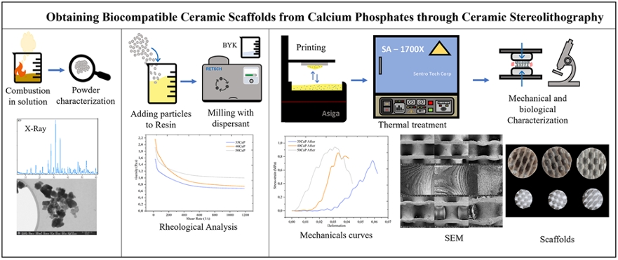
Ceramic stereolithography scaffolds with designs based on triple periodic minimal surfaces (TPMS) were developed for potential applications in bone tissue regeneration. An acrylic-based resin with calcium phosphate nanoparticles were used. Particles were synthesized via Combustion in solution, resulting in hydroxyapatite and β-TCP phases. Suspensions with 35, 40, and 50 vol% particles, using a 10 wt% of dispersant, were prepared and rheologically characterized to ensure suitable viscosities for printing, and were used to print gyroid scaffolds by DLP technique. The suspension with the highest ceramic load demonstrated the highest viscosity. The green bodies were morphologically and mechanically characterized before and after sintering. Volumetric shrinkage, morphological characteristics by digital and FE-SEM images, and compressive strength were evaluated. Polymeric-ceramic (Hybrid) scaffolds before sintering exhibited better compressive strength than sintered ones. Ceramic scaffolds achieved compressive strength values up to 0.9 MPa, comparable to those of cancellous and cortical bone. The optimal scaffolds (50CPF) were subjected to degradation tests in PBS and were impregnated with ethanolic extract of propolis from Arauca, Colombia, for biological analysis using the L929 cell line. The results indicate that ceramic stereolithography is an effective technique to produce scaffolds with optimal characteristics for potential applications in bone tissue regeneration.
Graphical Abstract
1 Introduction
Bone trauma and diseases are very common around the world and often require partial repairs or complete replacements, which are complex and expensive treatments [1]. One solution is the use of autografts, but this method can compromise the function of healthy organs or tissues, has a long production and acquisition cycle, and may produce grafting material that is insufficient or inappropriate size and shape [2, 3]. Consequently, there is a significant focus on developing novel treatments and techniques for bone tissue regeneration, including the use of materials to produce implantable devices with properties similar to bone in terms of mechanical strength and biocompatibility [4, 5].
Implantable devices, known as scaffolds, need a porous structure with adequate size and pore interconnection to provide cell migration, vascularization, oxygen and nutrient flow, and residue elimination [5]. Additionally, scaffolds must support loads, a primary function of bone tissue. Geometries based on triple periodic minimal surfaces (TPMS) have been studied to satisfy these requirements, as their designs ensure interconnected porosity and controlled pore size. The curvature of TPMS structures influences cellular performance and fluid permeability significantly [1, 6]. One of the best known TPMS structures is the gyroid, which separates spaces into two opposing and congruent labyrinths of passages [7]. This structure can provide good mechanical resistance and an elastic modulus comparable to natural cancellous bone. Cells seeded in gyroid structures show better cell viability compared to other TPMS geometries, as their design allows greater cell penetration and better flow of the medium through their porosities [1, 8].
Geometries such as TPMS are difficult to produce using conventional manufacturing techniques. Additive manufacturing or 3D printing is a strategic tool to create these complex shapes [9]. Stereolithography (SLA) and digital light processing (DLP) stand out among 3D printing techniques for their ability to efficiently produce high-precision pieces [6], making them and attractive candidate for the creation of scaffolds for bone regeneration. These systems use a photocurable resin that polymerizes layer by layer upon light exposure. The DLP system ensures simultaneous light irradiation across the desired cross-section, reducing processing time compared to SLA, which uses a laser [5].
In the SLA and DLP processes, the CAD file of the prototype undergoes a slicing procedure to create layers. This information is sent to the machine, which projects each horizontal section onto the liquid resin using masks. The machine’s mobile platform starts at the bottom of the Z-axis, submerged in the vat containing the liquid resin, leaving a thin layer of material between the bottom of the vat and the platform. Upon exposure to UV light, this layer solidifies, forming the desired shape and thickness. The platform then rises with the solidified layer, allowing the resin to refill the vat, and submerges back to repeat the process until all sections of the object are solidified [10].
In these techniques, the photocurable resin can be modified by adding ceramic particles to produce hybrid (polymer/ceramic) or fully ceramic pieces. In the latter case, the particles are surrounded by the crosslinked polymer during printing. Once printed, the green body is subjected to thermal treatment to remove the resin and sinter the ceramic [11, 12]. High solid loads must be used to avoid crack formation during thermal processing, with a careful viscosity control to ensure self-leveling during printing. Nanometric ceramic particles improve the mechanical properties of the final piece but present challenges in preparing the mixture due to their high specific surface area and greater tendency to agglomerate [12]. In the ceramic SLA process, several essential steps are necessary to obtain fully ceramic pieces. These steps include preparing the photopolymerizable resin-ceramic suspension, printing the piece, debinding the resin, and sintering the green ceramic body. The objective is to achieve a high density of ceramic particles to produce pieces with good dimensional and structural integrity and to ensure proper sintering once the resin debinding process is complete [13].
Materials used to create scaffolds for bone repairs include a wide range of ceramics, polymers, and composite materials [14]. Depending on their ability to stimulate bone tissue, materials are classified as bioinert or bioactive. Bioactive materials include natural polymers like collagen, ceramics like calcium phosphates or bioactive glasses [15]. Calcium phosphates have shown great potential due to their biocompatibility, performance, degradability [16], mechanical stability, and composition, which is very similar to bone tissue, favoring cell adhesion, proliferation and promoting mineralization [17].
Scaffolds, as implantable devices, have demonstrated their efficacy in bone regeneration processes. The addition of natural compounds has been studied to confer properties that some scaffold materials by themselves could not provide, such as antibacterial activity or enhanced biocompatibility and bioactivity [18]. Propolis, a resinous substance produced by bees, has been used for treating many diseases and surgical repairs due to its biological activity [19]. These are produced by bees from various waxes, gums, pollen, and sap found in plants surrounding the hives and used by bees to protect them from the cold and some plagues [20]. The flora around the hive influences in the propolis properties, which vary geographically [21]. Some propolis have been described as potential antioxidants with antibacterial activity [22, 23] and may be considered anti-inflammatory and tissue restorers, promoting wound healing and serving as good alternatives for tissue regeneration [19, 24, 25].
In this work, a composite of acrylic resin with calcium phosphate particles, using a dispersant, was developed for implementation in ceramic SLA printing of gyroid TPMS ceramic scaffolds for potential biomedical applications. The resin was characterized, and the rheological behavior of the resin-calcium phosphate mixture with different ceramic load percentages was studied to ensure favorable printing conditions. High-quality gyroid geometries were obtained. These scaffolds were subjected to a controlled thermal treatment to remove the resin and achieve ceramic sintering. The resulting ceramic scaffolds were morphologically and mechanically characterized. The scaffolds with the percentage of ceramic load that presented the best mechanical behavior were selected for degradation tests and impregnation with propolis extracts from Arauca, Colombia, to evaluate cytotoxicity and proliferation of the L929 cell line on these samples.
2 Materials and methods
2.1 Resin and calcium phosphate particles
For the fabrication of scaffolds via vat photopolymerization, a commercial, pigment-free Portux Print 3D Model resin (New Stetic) was used. This resin was previously analyzed and characterized in a previous work [10] using Differential Scanning Calorimetry (DSC) and thermogravimetry (TG) with a TA Instruments Discovery 550 with air atmosphere and a heating ramp of 10 °C/min up to 1000 °C. Fourier Transform Infrared Spectroscopy (FTIR) was performed using a Shimadzu IRTracer-100 with an accessory to measure transmittance before and after curing. The FTIR spectra were acquired in a spectral range of 500–4000 cm−1.
The calcium phosphate particles used in the resin-ceramic suspension for printing were synthesized using the combustion in solution method, as detailed in a previous study [26]. Calcium nitrate tetrahydrate (Ca(NO3)2·4H2O, Merck) and ammonium hydrogen phosphate ((NH4)2HPO4, Alfa Aesar) were used as precursor raw materials for calcium and phosphorus, respectively. Glycine (C2H5NO2, Merck) was used as fuel, and nitric acid (HNO3) as a catalyst. Unlike the procedure in [26], the ashes were not thermally treated and were used directly for mixing and printing. The ashes were manually ground for 5 min and then subjected to a deagglomeration process in a ball mill (Retsch PM 100) for 15 min at 250 rpm with 5-min intervals and reverse rotation. The ashes were evaluated using X-ray diffraction with a double circle multipurpose Xpert-Pro PANanalytical Radiation Cu-Ka (λ = 0.15406 nm) diffractometer in a range of diffraction of 10–50° (2θ) as is detailed in [26].
Particle size was measured by taking images with a field emission scanning electron microscope (FESEM) and analyzing them using ImageJ software to statistically count 200 particles. For image acquisition, the samples were fixed on graphite tape, given a thin gold (Au) coating using a DENTON VACUUM Desk IV, and analyzed with a Dual Beam Field Emission Scanning Electron Microscope (Beam FIB-FESEM, Thermo Fisher Scientific, model Socios 2 LoVac).
2.2 Suspension of calcium phosphate particles in resin
Suspensions with concentrations of 35 (35CPF), 40 (40CPF), and 50 (50CPF) vol% of calcium phosphate particles (ashes) were prepared. The mixing process was conducted in two stages using a ball mill (Retsch PM 100) over a total period of 6 h. In the first stage, the commercial Portux Print 3D Model resin (New Stetic) was mixed with a dispersant, Disperbyk-167 (Altana), with 10 wt% of the ceramic load. This stage lasted 2 h at 250 rpm, with 30 s pauses every 5 min and reverse rotation. In the second stage, the ceramic powder was added at the required concentration for each batch, and the mixture was returned to the mill under the same conditions for an additional 4 h to achieve a homogeneous mixture. The resulting suspensions were rheologically characterized using shear rate vs. viscosity curves on a Bohlin Visco88BV viscometer (Bohlin Instruments).
The 50CPF suspension was also subjected to a thermogravimetric analysis (TG) and DSC using a TA Instruments Discovery 550 with air atmosphere and a heating ramp of 10 °C/min from room temperature to 1200 °C. This analysis was performed to determine the thermal behavior of the suspension with the highest ceramic load. For this purpose, a specimen with a diameter of 4 mm and a height of 1.5 mm, was printed on the same machine used for printing the scaffolds and used the same printing parameters.
2.3 Fabrication of the scaffolds
In this work, the Asiga PICO2GD printer, which operates using DLP methodology with a light source wavelength of 385 nm, was used. The printing parameters and slicing were configured using Asiga Composer software, with a layer thickness of 0.05 mm, an exposure time of 68 s for the initial layers, and 15 s for the subsequent layers. The selected TPMS geometry for the scaffolds was a gyroid, as shown in Fig. 1a. These scaffolds had an external cylindrical shape with a diameter of 10 mm, a height of 8 mm, and a porosity of 80.5 vol%. The porosity was measured using images of the different kind of samples, the ImageJ software, and a CAD model image to calculate the material and pore volumes. It is important to note that the porosity referred to in this section is macroscopic, resulting from the TPMS geometry.
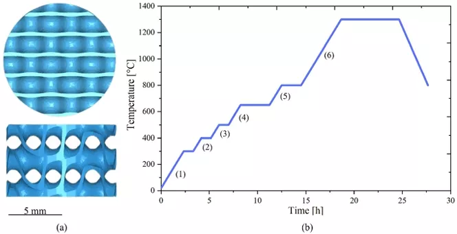
Fig. 1 CAD Model Image and Thermal Treatment Curve. a Top and side view of the CAD model of the gyroid geometry, b Thermal treatment curve to which the 35CPF, 40CPF, and 50CPF samples were subjected
The interconnected pores of the TPMS structures can be described using trigonometric functions. These were modeled using MathMod® software in a previous study [27]. Initially, a unit cell of the TPMS was created and replicated in three dimensions, three times along the XY axes and twice along the Z-axis, resulting in surfaces consisting of a total of 18-unit cells.
2.4 Post-processing of green ceramic bodies
Once the samples were printed, they were cleaned for 3 min in isopropyl alcohol and were subjected to a post-curing process with an Anycubic Wash & Cure Plus machine (Anycubic, China) at a wavelength of 405 nm for 50 min. Subsequently, the samples were subjected to thermal treatment in an SA-1700X furnace (Sentro Tech Corp, USA) for debinding and subsequent sintering of the ceramic material. The thermal treatment curve used is shown in Fig. 1b and the ramps information is shown in Table 1. The heating of the furnace, where the samples were located, started at room temperature (25 °C). The maximum temperature reached was 1300 °C. The temperature was raised gradually with pauses of about 1 h every 100 °C to ensure the complete and gradual degradation of the resin. The temperature was maintained for 2 h at 800 °C to ensure the phase change of the calcium phosphates. There were six ramps numbered from 1 to 6 in Fig. 1b. Once the samples were sintered after 6 h at 1300 °C, the cooling was performed slowly following the oven conditions until reaching room temperature (25 °C).
Table 1 Heat treatment curve ramps
The sintered ceramic bodies were characterized by X-ray diffraction using a double-circle Xpert-Pro PANalytical diffractometer with Cu-Kα radiation (λ = 0.15406 nm) in a diffraction range of 10–50° (2θ).
2.5 Scaffolds properties
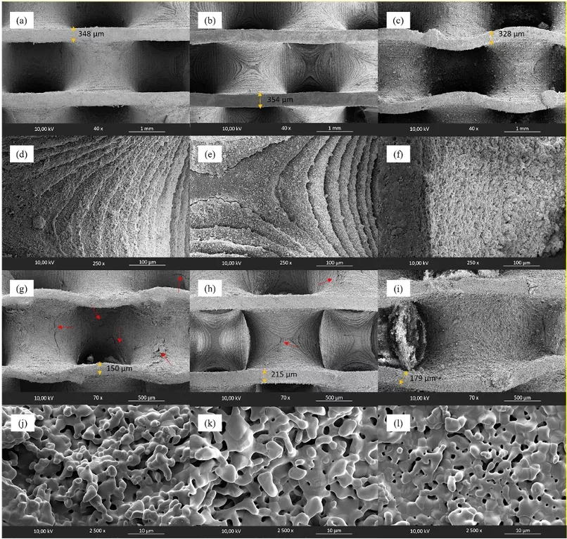
The calcium phosphate scaffolds produced via DLP were characterized before and after the thermal treatment for resin debinding and sintering. Field emission scanning electron microscopy (FESEM) was used for imaging. The samples were fixed on graphite tape, given a thin gold (Au) coating using a DETON VACUUM desk IV machine and analyzed with a dual beam field emission scanning electron microscope (Beam FIB-FESEM, Thermo Fisher Scientific, model Socios 2 LoVac).
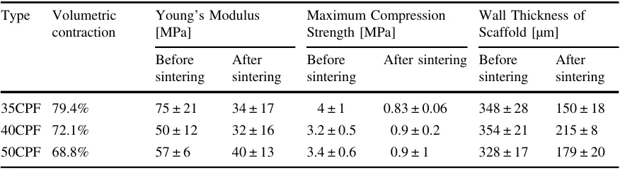
To calculate the volumetric shrinkage percentage during thermal treatment, the external dimensions (diameter and height) of both kind of samples (before and after sintering) were measured with an analog caliper (Discover Tools, China). The theoretical volume of the geometry was also measured using the CAD file in ImageJ software, as well as the wall thicknesses of the CAD model, the printed scaffolds, and the scaffolds after sintering.
2.5.1 Mechanical tests
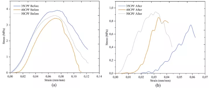
Mechanical compression strength tests were conducted on the scaffolds before and after sintering using a universal testing machine (Instron 3366, Instron, MA, USA) with a constant displacement rate of 1 mm/s. Measurements were taken on five scaffolds from each concentration under identical conditions. The Young’s modulus of the samples was obtained from the slope of the linear section of the stress-strain curve for each test, while the maximum compressive strength of the samples was measured as the maximum stress value reached by each test sample.
2.5.2 Degradation test
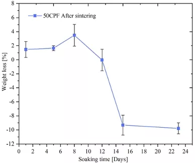
An in vitro degradation test was made in accordance with ASTM F 1635-16 to study the weight loss of 50CPF scaffolds post-sintering over a 23-day period. The scaffolds were immersed in phosphate-buffered saline (PBS) solution (pH 7.4, Sigma-Aldrich, USA). Measurements were taken on days 1, 5, 8, 12, 15, and 23. Each sample was individually immersed in 20 ml of PBS within sealed polyethylene containers and incubated at 37 °C with 5% CO2 (Thermo Scientific, USA). On each evaluation day, the pH of the PBS was measured using a PH700 pH meter (Apera, USA). Samples were then removed from the PBS, rinsed with distilled water, and dried at 30 °C for 15 min in an oven (Binder, Germany). Once dried, the samples were weighed using a balance (Adam Equipment, UK). The mass loss was calculated using Eq. 1. Each measurement was performed in triplicate to ensure accuracy and reliability.

Where W0 is the initial dry weight of the sample and Wt is the dry weight of the sample after the selected time.
2.5.3 Impregnation of Sintered Scaffolds with Propolis
The printed and sintered 50CPF scaffolds were impregnated with ethanolic extracts of propolis from Arauca, Colombia, at a concentration of 0.7 mg/mL, obtained from a previous study [23]. Initially, 20 µL of the ethanolic propolis extract was deposited on the surface of each scaffold. The scaffolds were then placed in a positive pressure chamber (Wiropress, BEGO, Germany) for 5 min at 2.4 Bar. The absorption of the extract by the scaffolds was confirmed by observing a color change in the scaffolds and by checking the moisture of a napkin placed under the samples. This process was repeated until a total volume of 80 µL was impregnated into each scaffold.
2.5.4 Biological assays
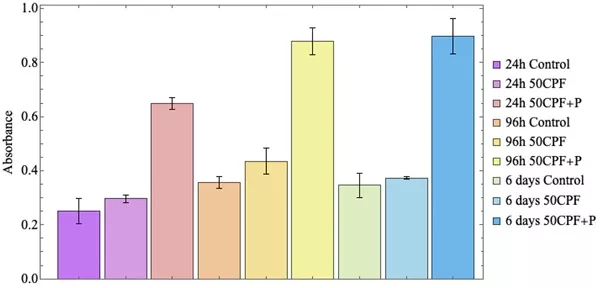
To evaluate bioactivity, two groups of samples were used: scaffolds composed of 50 vol% of calcium phosphate impregnated with an ethanolic extract of propolis (50CPF + P) and unimpregnated scaffolds (50CPF). Both types of samples were sterilized with UV light before experimentation. A cytotoxicity assay using MTT was conducted in 24-well plates, with each well containing one scaffold of each type. Onto each scaffold, 50,000 cells from the L929 cell line (NCTC clone 929 [L cell, L-929, derivative of Strain L], ATCC Nr. CCL-1) were seeded using DMEM medium supplemented with 10% v/v fetal bovine serum (Gibco, USA). A control group with the same number of cells seeded without any scaffold was maintained to ensure proper cell growth. Measurements were taken at 24 and 96 h, as well as at 6 days. On each measurement day, the medium was removed, the wells and samples were washed with Ringer’s lactate to eliminate dead cells, the sample were moved to a different well, and MTT solution (1 mg/mL in DMEM medium) was added. The plates were then incubated for 2 h. After incubation, the absorbance at 570 nm of each well containing 50CPF and 50CPF + P scaffolds was measured using a spectrophotometer (Multiscan Go, Zeiss, Germany). Comparisons were made between the two scaffold types. All experiments and measurements were performed in triplicate.
2.6 Statistical analysis
The results were expressed as mean ± standard deviation (SD). Statistical analysis was performed using Minitab Statistical Software (Minitab Inc.). To assess the significance of differences between experimental groups, a multivariate analysis of variance (ANOVA) was conducted. A p-value of less than 0.05 was considered statistically significant. Graphs were generated using Wolfram Mathematica (Wolfram) and Origin (OriginLab Corporation) software.
3 Results and discussion
3.1 Characterization of ceramic powder
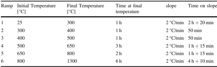
Figure 2a shows the histogram of particles and agglomerates size distribution (PSD) for the calcium phosphate (ashes) used in this study. The data indicates that 32.5% of the particles range in size from 20 to 40 nm, and 90% are smaller than 100 nm. Figure 2b highlights the presence of aggregates ~150 nm in size, composed of nanoparticles with granular or spherical morphology. Controlling the size of particles and aggregates in DLP printing is crucial, as their dimensions must be smaller than the layer thickness to avoid compromising the vertical resolution of the printed geometry [13]. In this study, most particles are smaller than the used layer thickness of 0.05 mm, ensuring that the printing resolution will not be affected.
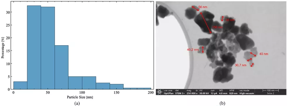
Fig. 2 Characterization of Calcium Phosphate Particles. a Resulting histogram from particle size measurements taken with ImageJ software and analyzed by Origin software of the particle size distribution of the calcium phosphate (ashes) used in the resin-ceramic mixture for DLP printing. b Example of FESEM image used for particle and aggregate size measurements

Declaration: This article is provided by CERADIR™ users or obtained from Internet, the content does not represent the position of CERADIR™. We are not responsible for the authenticity/accuracy of the article, especially the effects of the products concerned. This article is for study only, it does not constitute any investment or application advice. For reprinting, please contact the original author. If it involves the copyright and/or other issues, please contact us and we will deal with it asap! CERADIR™ has the interpretation of this declaration.