1.Laminated inductor elements and fabrication process
Laminated inductor(magnetic beads)is of ceramic membrane with electrode , composite in a certain way Pressurized cutting rubber, sintering to form a Monolithic structure, make the electrodes, and then made the laminated inductance(magnetic beads)or use stretch film (or printed) technology of ceramic membrane (or semiconductor ceramic membrane), composite (printing) in the form of a certain cutting adhesive, a sintering, make the electrode made of inductive components .
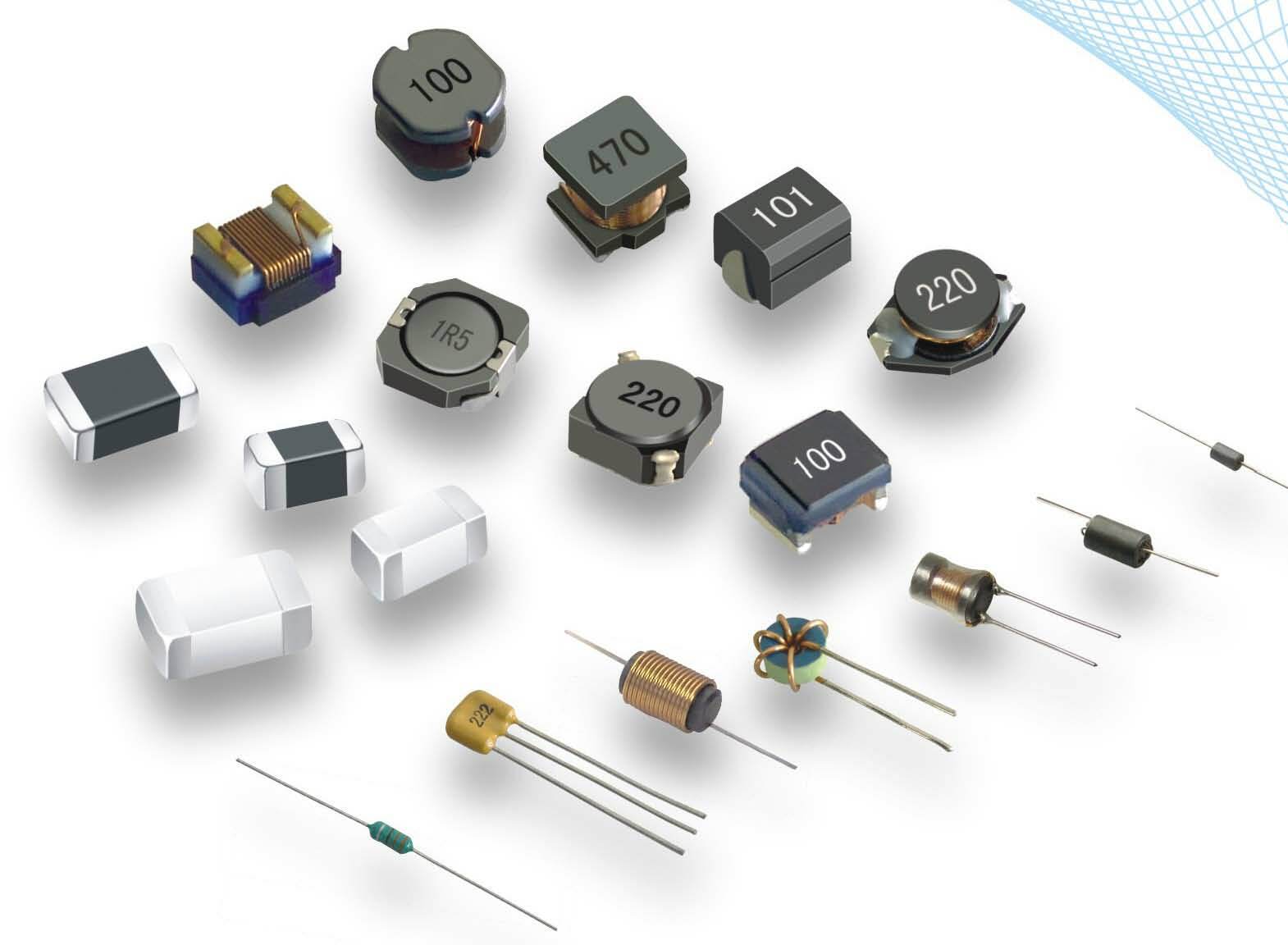
Laminated inductive elements
Lamination refers to the ceramic diaphragm produced by the flow (or printing) process, dozens or hundreds of electrode patterns are first printed, and then many layers of the diaphragm staggered overlapping, forming a rectangular or square laminated structure. At present, the more mature production process is the flow perforation method and alternate printing method.
Casting perforation method, that is, low temperature sintered medium materials and adhesives are made into slurry, using the casting process to make a dry diaphragm, in the set position with mechanical method through the hole,then print 3/4-week conductive electrode paste on the dry film,at the same time, the electrode paste is filled in the through hole. The dry film sheet of the printed conductive electrode paste is accurately positioned, laminated and pressurized to form a whole, cut into individual sheets on a precision cutting machine, and the binder is removed, and the monolithic structure is formed by co-firing at 900℃ After fabricating the terminal electrodes, a multilayer inductor is fabricated.
Alternate printing method, that is, the low-temperature sintered dielectric material is added with a binder to make a paste suitable for the screen printing process and printed into a dielectric film. On this film, the conductive electrode paste is printed for 3/4 weeks, and then the dielectric film is printed on the 1/2 area. In this way, the conductive electrode paste for 1/2 week is covered by the dielectric film, and the conductive electrode paste for 1/4 week is not covered by the dielectric film. cover. Continue to print the conductive electrode paste for 3/4 of a week, and connect it with the conductive electrode paste that was not covered by the last printing, thereby forming a loop conductor, separated by a dielectric film. Repeat this process to print into a laminated inductance structure, and then dry, precision cut, de-glue, and chamfer. Co-fired below 900°C to form a monolithic structure, and after making terminal electrodes, a multilayer inductor is made.
Declaration: This article is provided by CERADIR™ users or obtained from Internet, the content does not represent the position of CERADIR™. We are not responsible for the authenticity/accuracy of the article, especially the effects of the products concerned. This article is for study only, it does not constitute any investment or application advice. For reprinting, please contact the original author. If it involves the copyright and/or other issues, please contact us and we will deal with it asap! CERADIR™ has the interpretation of this declaration.